semi合集-English.pdf - 第478页
SEMI E68-0997 © SEMI 1997, 2003 3 Table 1 Format for Data Presentation Warm-up Time Date:____________ ± 1% FS Ti me to Achieve Steady St ate Steady St ate Value Cold Start Power Interruption 10.4 Cold Start — Apply power…
SEMI E68-0997 © SEMI 1997, 2003 2
8 Apparatus
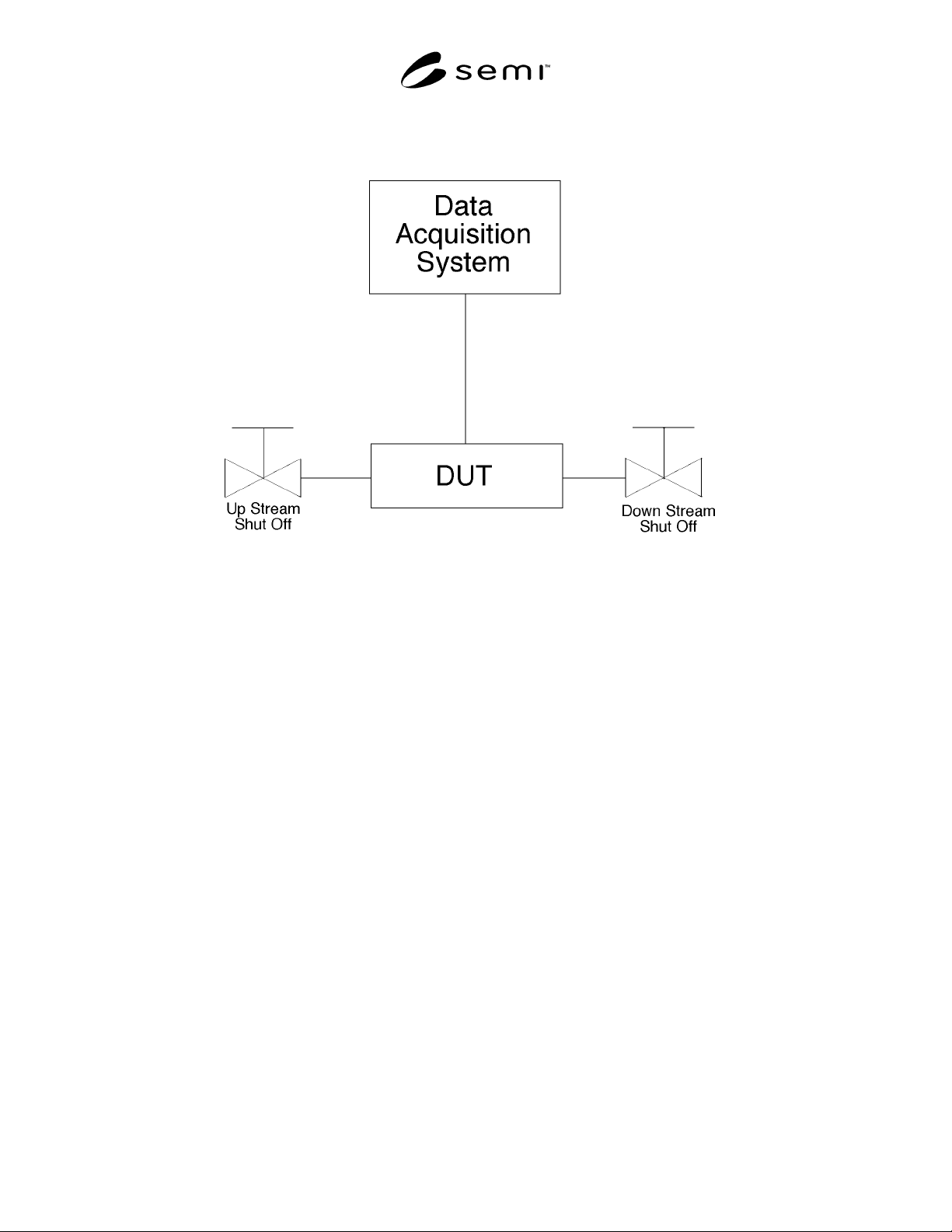
8.1 See Figure 1.
Figure 1
Test Set Up
8.2 Time-Keeping Apparatus — Capable of keeping accurate records within ± 10 seconds. Time-keeping
requirements are not stringent, and almost any apparatus is acceptable.
8.3 Data Acquisition System — Having a resolution of one mV or better and a sample rate of one Hz.
9 Conditioning
9.1 Ambient temperature must be controlled and stable between 20° C and 25° C during testing for all tests. The
DUT must be exposed to the ambient environment for 24 hours before the beginning of the test so that it is in
equilibrium. The gas temperature must be measured and verified to be at equilibrium with both the DUT and with
ambient temperature. Temperatures are in equilibrium if they are within 1° C of each other. Lab temperature may not
change more than 1° C during test.
10 Procedure
10.1 Connect the DUT in series with the two shut-off valves, one upstream of the DUT and the other downstream.
Electronically connect the DUT to a data acquisition system capable of recording indicated flow from the DUT. The
test set-up should be set to give appropriate signals to the DUT so the DUT control valve will not dissipate power.
For normally closed MFC’s, the setpoint should be zero, and for normally open MFC’s, the setpoint should be
100%. Suggested orientation of the DUT is horizontal (base down). If the DUT is positioned otherwise, the
orientation should be reported in the test data (see Figure 1). Valves are to be opened in a downstream-to-upstream
sequence and closed in reverse fashion. The data acquisition system must be warmed up as per the manufacturer’s
instructions.
10.2 Close shut-off valves.
10.3 In Table 1, record the time of day when power was applied to the DUT. Begin recording the indicated flow
from the DUT at one sample per second.
SEMI E68-0997 © SEMI 1997, 2003 3
Table 1 Format for Data Presentation
Warm-up Time Date:____________
± 1% FS Time to
Achieve
Steady State
Steady State
Value
Cold Start
Power Interruption
10.4 Cold Start — Apply power to the DUT and
continue collecting data until the indicated flow
achieves a steady state value.
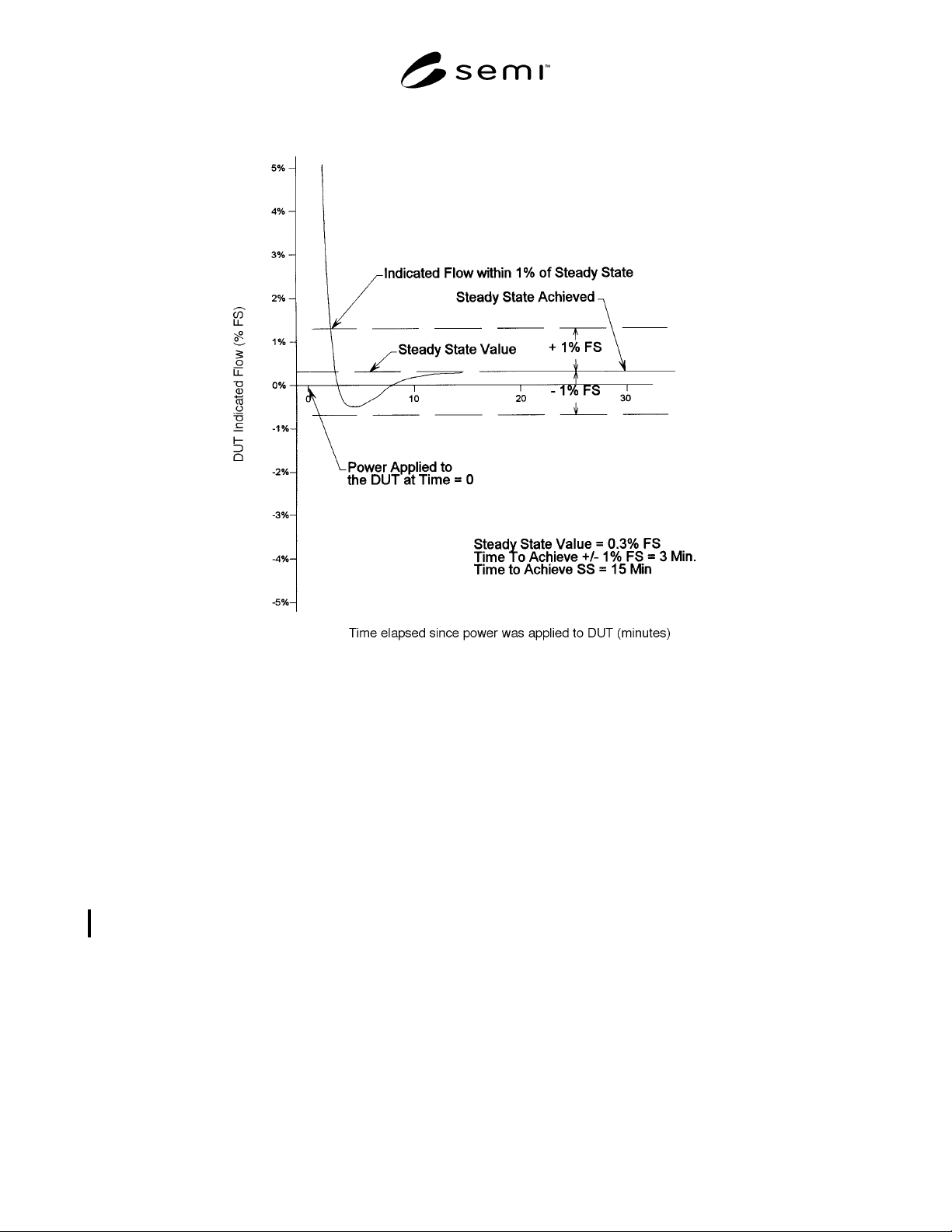
10.5 Power Interruption — Continue to collect data
while disconnecting power from the test unit for 120 ±
10 seconds. Reconnect power to the DUT and monitor
indicated flow until steady state is again achieved.
11 Data Analysis
11.1 Graph the data collected from the six test
scenarios as directed in Section 10.
11.2 The time required for the DUT to achieve a steady
state value can be visually determined from the graph
of each test scenario. This data can be used to predict
the warm-up times required by an MFC experiencing a
field condition similar to the test scenario.
12 Data Presentation
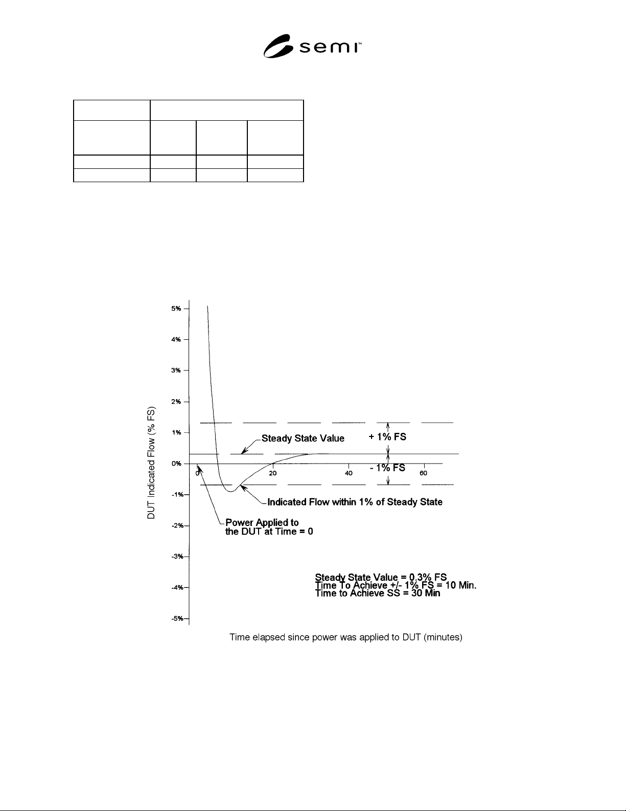
12.1 For the two tests in Section 10, plot DUT
indicated flow vs. time as illustrated in Figures 2 and 3.
Note the following on these graphs and in Table 1.
Figure 2
Cold Start Warm-Up Time
SEMI E68-0997 © SEMI 1997, 2003 4
Figure 3
Two-Minute Power Interruption Warm-Up Time
12.1.1 Final steady-state value of the DUT.
12.1.2 Time to achieve a steady state value.
12.1.3 Use Table 1 to summarize warm-up times associated with each of the test scenarios.
13 Precision and Bias
13.1 Precision and bias in this test are a function of the uncertainty of the measurement equipment used. The tester
or end user is responsible for determining the precision and bias of a particular setup and test.
NOTICE: SEMI makes no warranties or representations as to the suitability of the standards set forth herein for any
particular application. The determination of the suitability of the standard is solely the responsibility of the user.
Users are cautioned to refer to manufacturer’s instructions, product labels, product data sheets, and other relevant
literature respecting any materials mentioned herein. These standards are subject to change without notice.
The user’s attention is called to the possibility that compliance with this standard may require use of copyrighted
material or of an invention covered by patent rights. By publication of this standard, SEMI takes no position
respecting the validity of any patent rights or copyrights asserted in connection with any item mentioned in this
standard. Users of this standard are expressly advised that determination of any such patent rights or copyrights, and
the risk of infringement of such rights, are entirely their own responsibility.
Copyright by SEMI® (Semiconductor Equipment and Materials
International), 3081 Zanker Road, San Jose, CA 95134. Reproduction o
f
the contents in whole or in part is forbidden without express written
consent of SEMI.