semi合集-English.pdf - 第6538页
SEMI G81-0703 © SEMI 2000, 2003 13 NOTICE: SEMI makes no warranties or representations as to the su itability of the standard set forth herein for any particular application . The determinati on of the suitability o f th…
SEMI G81-0703 © SEMI 2000, 2003 12
APPENDIX 3
TRAY MAP ORIENTATION
NOTICE: The material in this appendix is an official part of SEMI G81 and was approved by full letter ballot
procedures on August 27, 2001.
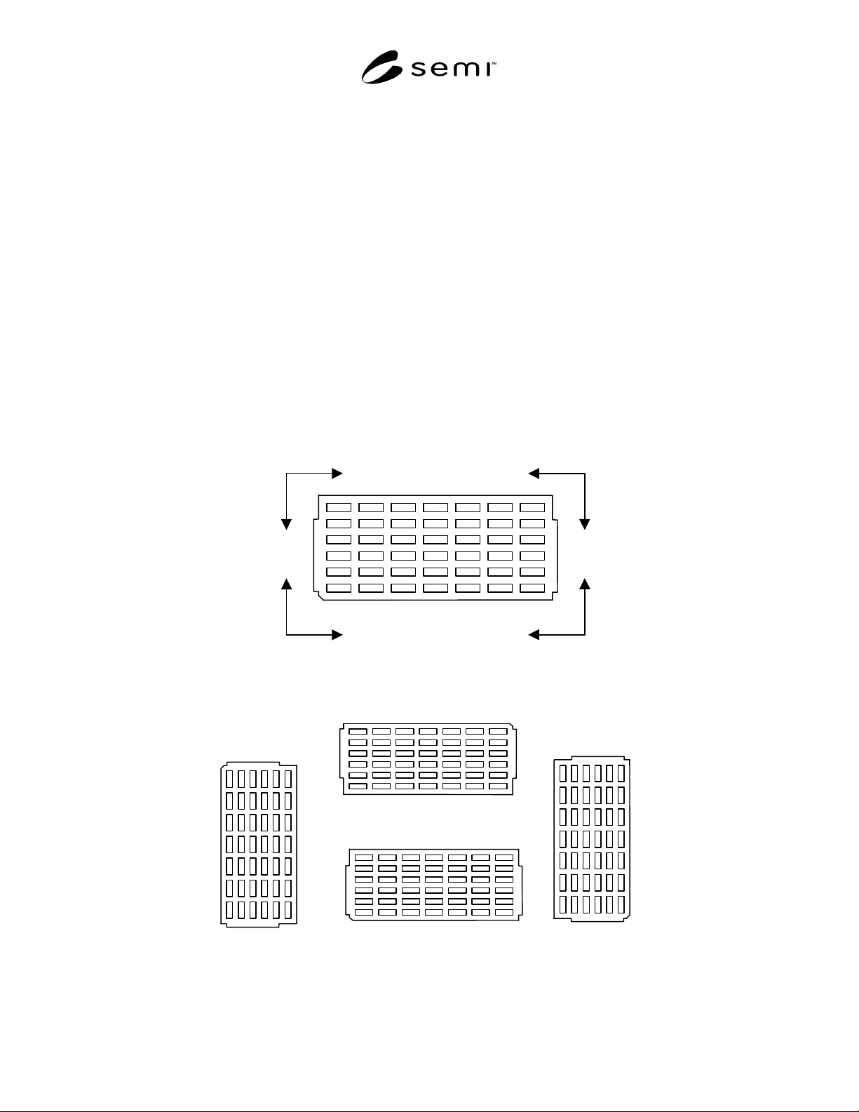
A3-1 This appendix shows how the map data items may be applied to JEDEC trays as well as some additional
information specific to this substrate type.
A3-2 The X-axis (Column) is assigned to the long axis of the JEDEC tray; the Y-axis (Row) is assigned to the short
axis of the tray. This corresponds to Cartesian coordinate “1” (in this way all coordinate positions can be expressed
in positive integer values). For the origin of the tray, the pocket nearest the bevel (at the bottom left corner of the
tray in Figure A3-1 below) is defined as coordinate location 0,0. (Row/Column).
A3-3 The following values for OriginLocation apply to the JEDEC tray:
1 = Upper right (UR) top side
2 = Upper left (UL) top side
3 = Lower left (LL) top side
4 = Lower right (LR) top side
Column
Row
Row
Row
Row
Column
Column Column
Upper right top side
Lower right top side
Upper left top side
Lower left top side
Figure A3-1
OriginLocation
180 Deg.
270 Deg.
90 Deg.
0 Deg.
Figure A3-2
Tray Orientation

SEMI G81-0703 © SEMI 2000, 2003 13
NOTICE: SEMI makes no warranties or representations as to the suitability of the standard set forth herein for any
particular application. The determination of the suitability of the standard is solely the responsibility of the user.
Users are cautioned to refer to manufacturer’s instructions, product labels, product data sheets, and other relevant
literature respecting any materials mentioned herein. These standards are subject to change without notice.
The user’s attention is called to the possibility that compliance with this standard may require use of copyrighted
material or of an invention covered by patent rights. By publication of this standard, SEMI takes no position
respecting the validity of any patent rights or copyrights asserted in connection with any item mentioned in this
standard. Users of this standard are expressly advised that determination of any such patent rights or copyrights, and
the risk of infringement of such rights, are entirely their own responsibility.
Copyright by SEMI® (Semiconductor Equipment and Materials
International), 3081 Zanker Road, San Jose, CA 95134. Reproduction o
f
the contents in whole or in part is forbidden without express written
consent of SEMI.

SEMI G82-0301
E
© SEMI 2001 1
SEMI G82-0301
E
PROVISIONAL SPECIFICATION FOR 300 mm LOAD PORT FOR
FRAME CASSETTES IN BACKEND PROCESS
This specification was technically approved by the Global Assembly & Packaging Committee and is the
direct responsibility of the Japanese Packaging Committee. Current edition approved by the Japanese
Regional Standards Committee on December 1, 2000. Initially available at www.semi.org December 2001,
to be published March 2002.
E
This document was editorially modified in November 2001 to correct a cosmetic error. Changes were made
to Figure 2.
1 Purpose
1.1 This specification defines dimensional
requirements for the load port of frame cassette for 300
mm wafer in backend process equipment. It is intended
to promote a uniform physical interface between
equipment and the factory, to facilitate the use of
automated frame cassette transport systems, and/or to
meet ergonomic requirements for manually loaded
equipment.
2 Scope
2.1 This is a provisional standard covering equipment
for 300 mm frame cassette only. The provisional status
is dictated by the immaturity of designs for 300 mm
equipment and additional specifications which are not
defined yet.
2.2 These standards do not purport to address safety
issues, if any, associated with their use. It is the
responsibility of the user of these standards to establish
appropriate safety and health practices and determine
the applicability of regulatory limitations prior to use.
3 Limitations
3.1 This standard is not intended for use in backend
except frame cassette for 300 mm wafers. This standard
does not address direct loading/unloading of vacuum
load locks. Requirements of such interfaces may differ
from those in this document.
4 Referenced Standards
4.1 SEMI Standards
SEMI E15 — Specification for Tool Load Port
SEMI E15.1 — Specification for 300 mm Load Port
SEMI E57 — Mechanical Specification for kinematic
Couplings Used to Align and Support 300 mm Wafer
Carriers
SEMI E64 — Specification for 300 mm Cart to SEMI
E15.1 Docking Interface Port
SEMI G77 — Specification for Frame Cassette for 300
mm Wafers
5 Terminology
5.1 Please see SEMI G77 for definitions of the
following terms used in this specification:
5.1.1 bilateral datum plane
5.1.2 conveyor rails
5.1.3 facial datum plane
5.1.4 frame cassette
5.1.5 horizontal datum plane
5.1.6 tape frame
5.2 Please see SEMI E15 for definitions of the
following terms used in this specification:
5.2.1 load depth
5.2.2 load face plane
5.2.3 load height
5.2.4 load port
5.2.5 spacing
5.2.6 tool
5.3 frame cassette centroid — a datum representing the
theoretical location of the center of a stack of tape
frames in the frame cassette.
6 Ordering Information
6.1 The following items require communication
between the tool supplier and user and shall be included
in any request for quotation or purchase order:
6.1.1 If the tool has multiple load ports, provide the
spacing, S, between frame cassette centroids (see SEMI
E15).
6.1.2 Specify what frame cassette (e.g. optional
composition, see SEMI G77) is to be accommodated by
the load port (see SEMI E15).