semi合集-English.pdf - 第6913页
SEMI S8-0705 © SEMI 1995, 2005 10 Section Indicator Acceptance Criteria Metric Units (US Customary Units) Actual Conforms/Does N ot Conform/Not Applicable 3.5 Minimum hand clearance on eith er side of the cassette, meas …
SEMI S8-0705 © SEMI 1995, 2005 9
APPENDIX 1
SUPPLIER ERGONOMIC SUCCESS CRITERIA (SESC)
NOTICE: The material in this appendix is an official part of SEMI S8 and was approved by full letter ballot
procedures by the North American Regional Standards Committee.
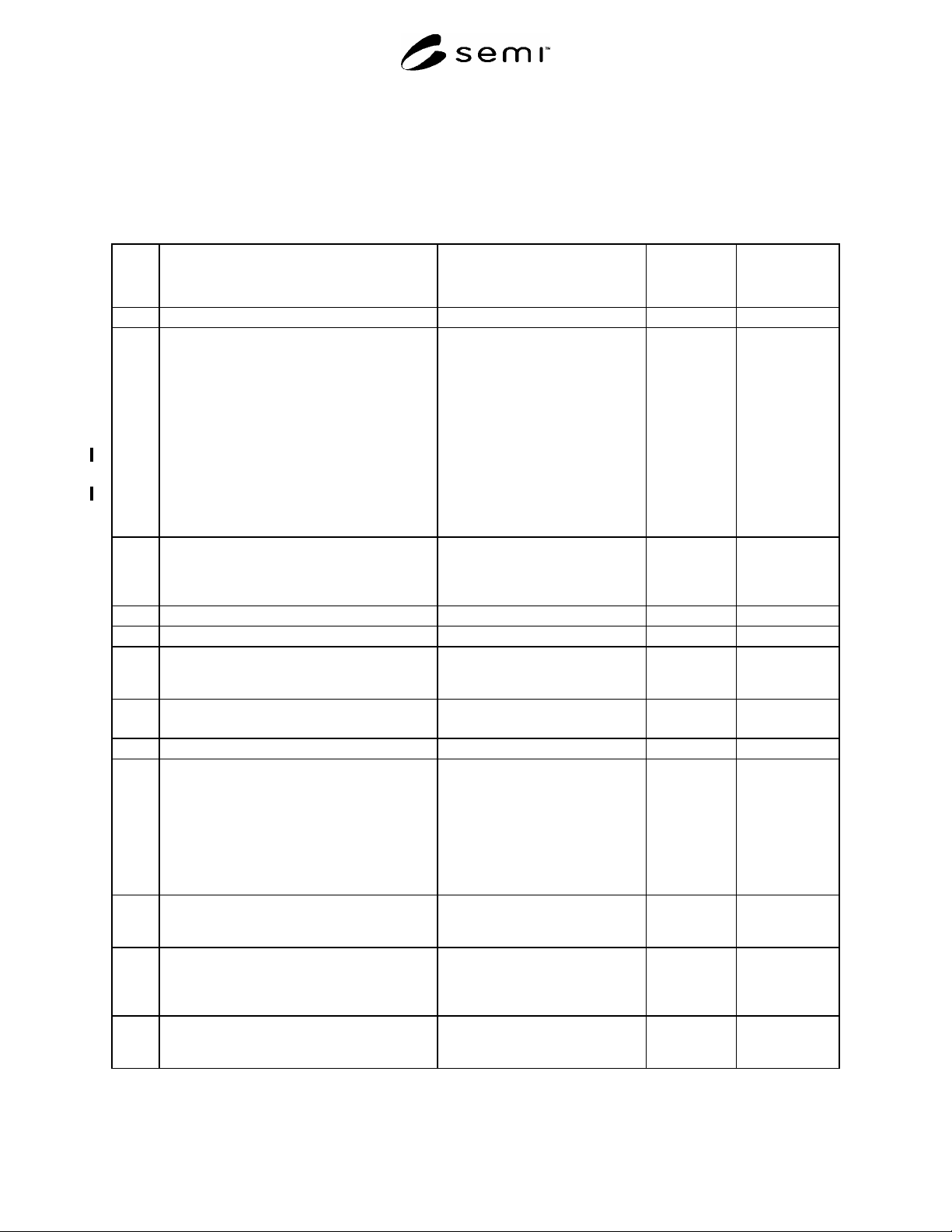
Table A1-1 Supplier Ergonomic Success Criteria Checklist
Section Indicator
Acceptance Criteria
Metric Units (US Customary Units)
Actual
Conforms/Does
N
ot Conform/Not
Applicable
1 Manual Material Handling
1.1 Potentially hazardous manual material handling
tasks performed as part of operations,
maintenance, or service are analyzed utilizing
appropriate procedures.
NOTE: Two hand lifting or lowering tasks
should be analyzed:
if the object being handled weighs more than
44.5 N (10 lbf);
OR, if the object weighs more than 22.2 N
(5 lbf) and the anticipated frequency is greater
than 1 lift every 5 minutes.
See Appendix 2 for further information.
Analysis and results
documentation. Table A2-2,
Appendix 2, or the equivalent,
should be used to document 2 hand
lift/lower analysis.
2 Product Loading in a Standing Posture
(Applicable to all media other than wafer
cassettes including JEDEC trays, magazines,
and reticle cassettes.
2.1 Clearance provided for finger thickness. minimum 38 mm (1.5 in.)
2.2 Clearance provided for hand thickness. minimum 76 mm (3.0 in.)
2.3 Reach distance measured from the leading edge
of the tool or obstruction to the hand/product
coupling point(s).
maximum 330 mm (13 in.)
2.4 Vertical coupling point of hand to product in
load position
maximum 1010 mm (40 in.)
minimum 890 mm (35 in.)
3 Wafer Cassette Loading
3.1 Wafer cassette loading should not require
greater than 10 degrees cassette rotation in any
axis.
NOTE: Unless otherwise specified, you should
assume that 200 mm or smaller wafers are
transported in the vertical orientation and that
300 mm wafers are transported in the horizontal
orientation.
less than 10 degrees rotation in any
axis
3.2 Load port height, vertical distance from
standing surface
(150–200 mm wafers).
maximum 960 mm (38 in.)
minimum 890 mm (35 in.)
3.3 Maximum lip height in front of cassette load
port over which cassette is lifted (150–200 mm
wafer cassettes only). Measure lip height from
the load surface.
maximum 30 mm (1.2 in.)
3.4 Reach distance from the leading edge of the tool
or obstruction to the coupling point(s) on
rotation device or the product grasp point.
maximum 330 mm (13 in.)
SEMI S8-0705 © SEMI 1995, 2005 10
Section Indicator
Acceptance Criteria
Metric Units (US Customary Units)
Actual
Conforms/Does
N
ot Conform/Not
Applicable
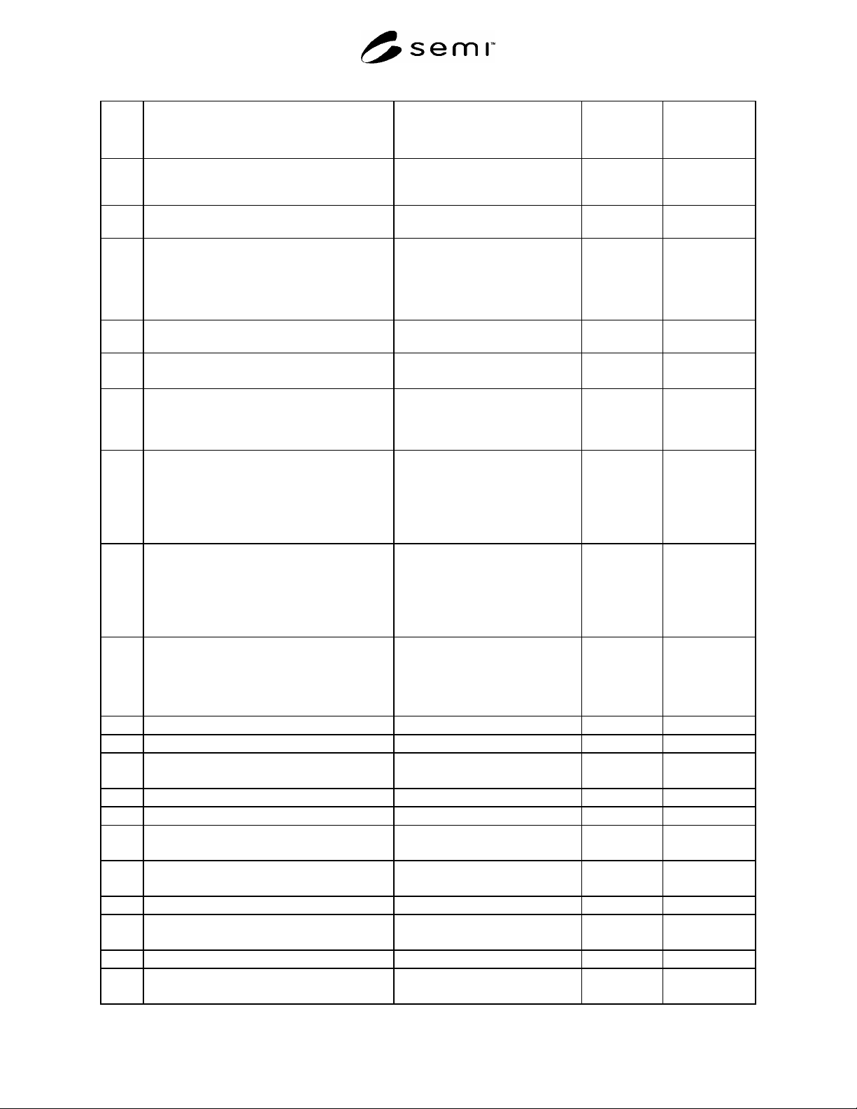
3.5 Minimum hand clearance on either side of the
cassette, measured from the side of the cassette
to the nearest adjacent object.
minimum 76 mm (3.0 in.)
4
Work in Process Storage (specific to wafer
cassettes)
4.1 Integral wafer cassette/lot box storage shelf
height (150 and 200 mm wafer cassette/lot
boxes only)
maximum (1 box deep) 1520 mm
(60 in.)
maximum (2 boxes deep) 1220 mm
(48 in.)
minimum 460 mm (18 in.)
5 Manual Wafer Cassette Rotation Device
Design
5.1 Handle height, couple point for hand(s) from
standing surface.
maximum 1206 mm (47.5 in.)
minimum 838 mm (33 in.)
5.2 Hand grip(s) shall allow for a full “power grip”
similar to grabbing a rung on a ladder or
holding a pistol.
Allows for a full power grip in
either pronated (palm facing down)
or neutral (handshake position)
posture.
5.3 Single hand lift force maximum 37.8 N (8.5 lb.) This
value includes a 15% capacity
reduction due to cleanroom glove
use.
Wrist deviation reduces further
strength capacity by 15%.
5.4 Two hand lift force maximum 64.5 N (14.5 lb.) This
value includes a 15% capacity
reduction due to cleanroom glove
use.
Wrist deviation reduces further
strength capacity by 15%.
6
Handle Design (Handle dimensions are correct
for use of bare hand or use of typical cleanroom
gloves)
NOTE: See Appendix 3 for depiction of handle
types.
6.1 Handle surface finish all edges radiused
6.2 Cylindrical handle
6.2.1 Cylindrical handle diameter (D) maximum 38 mm (1.5 in.)
minimum 25 mm (1.0 in.)
6.2.2 Cylindrical handle length (L) minimum 127 mm (5.0 in.)
6.3 Circular or triangular handle
6.3.1 Circular or triangular handle diameter (D) maximum 90 mm (3.5 in.)
minimum 50 mm (2.0 in.)
6.3.2 Circular or triangular handle height (thickness)
(H)
maximum 25 mm (1.0 in.)
minimum 19 mm (0.75 in.)
6.4 Ball handle
6.4.1 Ball handle diameter maximum 63 mm (2.5 in.)
minimum 38 mm (1.5 in.)
6.5 Pliers handle
6.5.1 Pliers handle grip span (S) maximum 89 mm (3.5 in.) open
minimum 38 mm (1.5 in.) closed
SEMI S8-0705 © SEMI 1995, 2005 11
Section Indicator
Acceptance Criteria
Metric Units (US Customary Units)
Actual
Conforms/Does
N
ot Conform/Not
Applicable
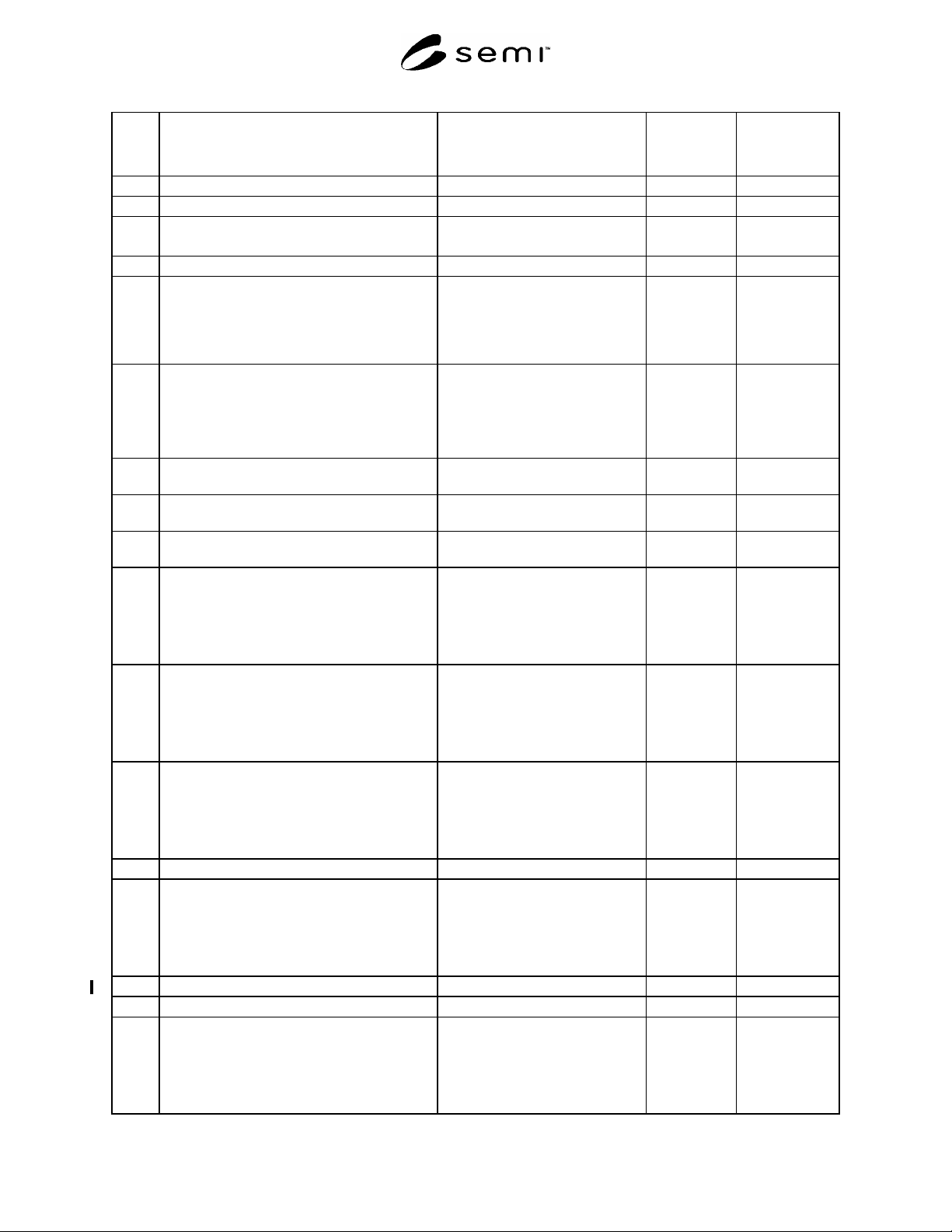
6.5.2 Pliers handle length (L) minimum 127 mm (5.0 in.)
6.6 Pistol grip handle
6.6.1 Pistol grip handle diameter (D) maximum 63 mm (2.5 in.)
minimum 38 mm (1.5 in.)
6.6.2 Pistol grip handle length (L) minimum 127 mm (5.0 in.)
6.7 Enclosed handles
NOTE: Handle diameter refers to the surface of
the handle presented to the inside of the curled
fingers. Enclosed handles need not be made
solely from cylindrical stock.
6.7.1 Enclosed handle, full hand power grip (suitcase
handle)
Width (W)
Depth (D)
Diameter (d)
minimum 127 mm (5.0 in.)
minimum 45 mm (1.75 in.)
maximum 25 mm (1.0 in.)
6.7.1.1 Diameter (d), requiring no greater than 71 N (16
lbf) force
minimum 6.3 mm (0.25 in.)
6.7.1.2 Diameter (d), requiring no greater than 89 N (20
lbf) force
minimum 13 mm (0.5 in.)
6.7.1.3 Diameter (d), requiring no greater than 180 N
(40 lbf) force
minimum 19 mm (0.75 in.)
6.7.2 Enclosed handle, three fingers
Width (W)
Depth (D)
Diameter (d)
Force
minimum 90 mm (3.5 in.)
minimum 38 mm (1.5 in.)
minimum 6.3 mm (0.25 in.)
maximum 71 N (16 lbf)
6.7.3 Enclosed handle, two fingers
Width (W)
Depth (D)
Diameter (d)
Force
minimum 60 mm (2.5 in.)
minimum 38 mm (1.5 in.)
minimum 6.3 mm (0.25 in.)
maximum 51 N (11.5 lbf)
6.7.4 Enclosed handle, one finger
Width (W)
Depth (D)
Diameter (d)
Force
minimum 38 mm (1.5 in.)
minimum 38 mm (1.5 in.)
minimum 3.2 mm (0.13 in.)
maximum 27 N (6 lbf)
6.8 Hook grasp handle
6.8.1 Hook grasp handle (four fingers)
Opening length (L)
Opening width (W)
Depth (d)
Lip length (l)
minimum 90 mm (3.5 in.)
minimum 38 mm (1.5 in.)
minimum 50 mm (2.0 in.)
minimum 50 mm (2.0 in.)
6.8.2 Hook grasp handle pull force (four fingers) maximum 80 N (18.0 lbf)
6.9 Finger pull handle
6.9.1 Finger pull handles (four fingers)
Opening length (L)
Opening width (W)
Depth (d)
Lip length (l)
minimum 90 mm (3.5 in.)
minimum 25 mm (1.0 in.)
minimum 19 mm (0.75 in.)
minimum 19 mm (0.75 in.)