semi合集-English.pdf - 第1469页
SEMI 30.1-0200 © SEMI 1998, 2000 44 The equipment first calculates Theta, using , for example, the f ormula: Θ= tan − 1 M A − M N 1 + MA MN where MA and MN are, respectiv ely, the slopes of th e lines connecting …
SEMI 30.1-0200 © SEMI 1998, 200043
• “M21” layouts are established within the M20P coordinate system and need not require any additional
alignment site data than is needed to establish the M20P coordinate system. However, as with M20P, additional
alignment may be necessary because of errors in either the pattern layout or the equipment’s ability to locate
features. Offset shall be used to report the location corrections that result from any within-element alignments.
R1-5 How an M20P Coordinate System Is Established on a Substrate
The following example is fairly basic. For this example, the M20P coordinate system has a zero translation from the
SEMI M20 coordinate system. Also, the equipment documentation states that 4 alignment sites are required. The
equipment does M20P alignment on two alignment sites and does a low resolution and then a high resolution
alignment at each site. Note that the specific alignment point is different at the two resolutions, so the coordinates
are slightly different. The alignment sites are defined to the equipment via the process program class named
“TABLE-ALIGN-DEF”, as detailed below. The order of the sites in “TABLE-ALIGN-DEF” is not important. The
sites are then selected via the CPNAME named “ALIGNLIST”, which is included in the PP-SELECT command.
The order of the sites listed in “ALIGNLIST” is important and is as-specified in the equipment’s documentation.
The first item is the alignment site for the first low resolution site, the second item is for the first high resolution site,
the third item is the second low resolution site, and the fourth is the second high resolution site.
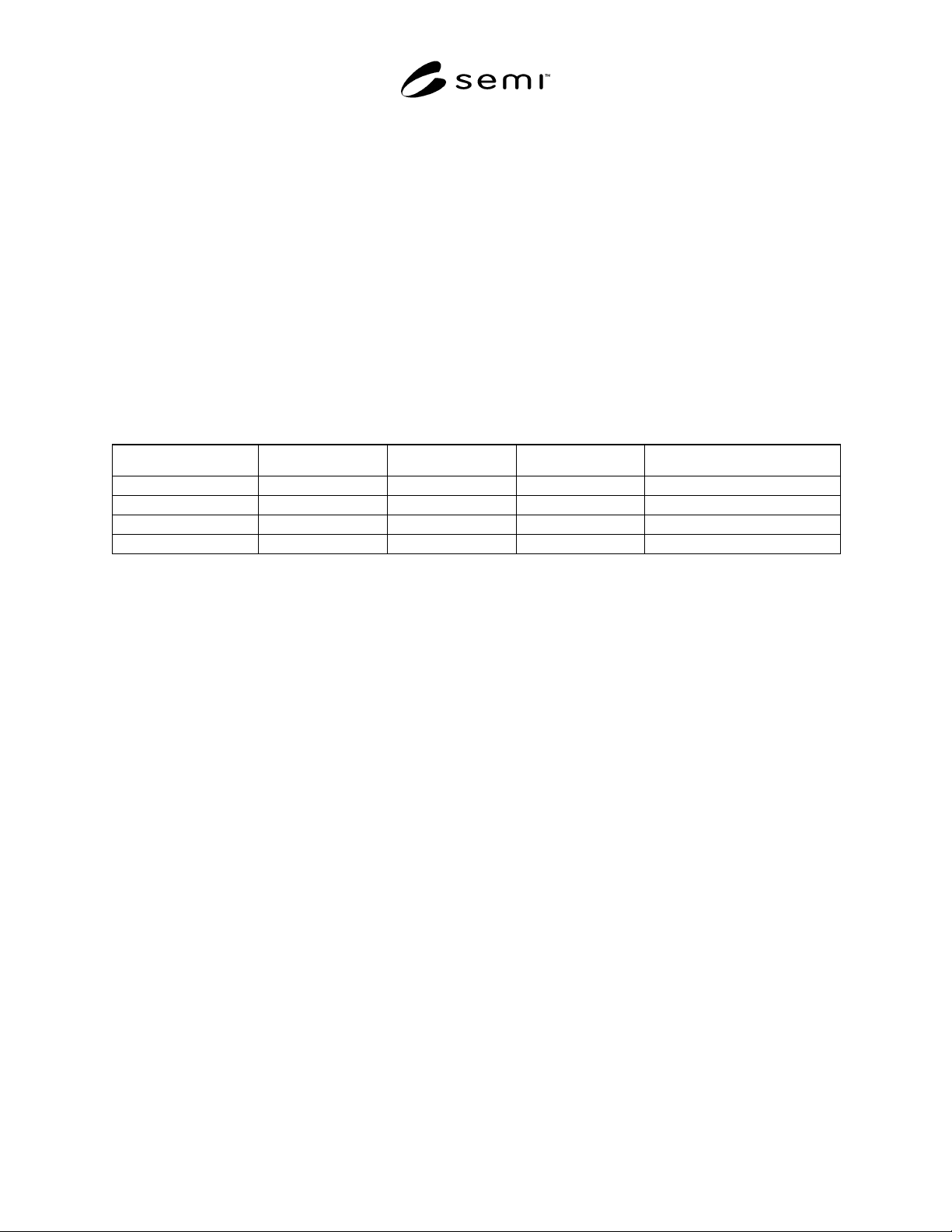
“TABLE-ALIGN-DEF”
AlignName Coordx Coordy Coordsys Attribute (1)
Coarse1 -60000 -200 “M20P”
Fine1 -60020 -205 “M20P”
Coarse2 +60000 +200 “M20P”
Fine2 +59980 +195 “M20P”
“ALIGNNAME”
L,4
1. <Coarse1>
2. <Fine1>
3. <Coarse2>
4. <Fine2>
Using this information, the equipment will go to the nominal “M20” location for Coarse1, then “find” where it
actually is. The offset between the nominal “M20” location and the actual “M20” location is then used to “find”
Fine1. The actual M20 location of Fine1 is saved. The process is then repeated for Coarse2 and Fine2. The
equipment can now determine the “M20” to M20P offset from the nominal and actual coordinates. First, a summary
of the data:
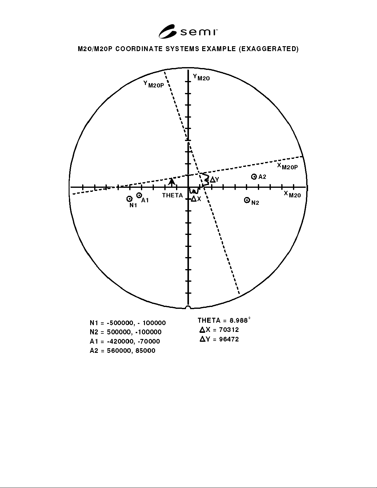
xN1 = -60020 yN1 = -205 Nominal x and y data for the first fine site
xA1 = -59800 yA1 = -150 Actual x and y data for the first fine site
xN2 = +59980 yN2 = +195 Nominal x and y data for the second fine site
xA2 = +60060 yA2 = +175 Actual x and y data for the second fine site
SEMI 30.1-0200 © SEMI 1998, 2000 44
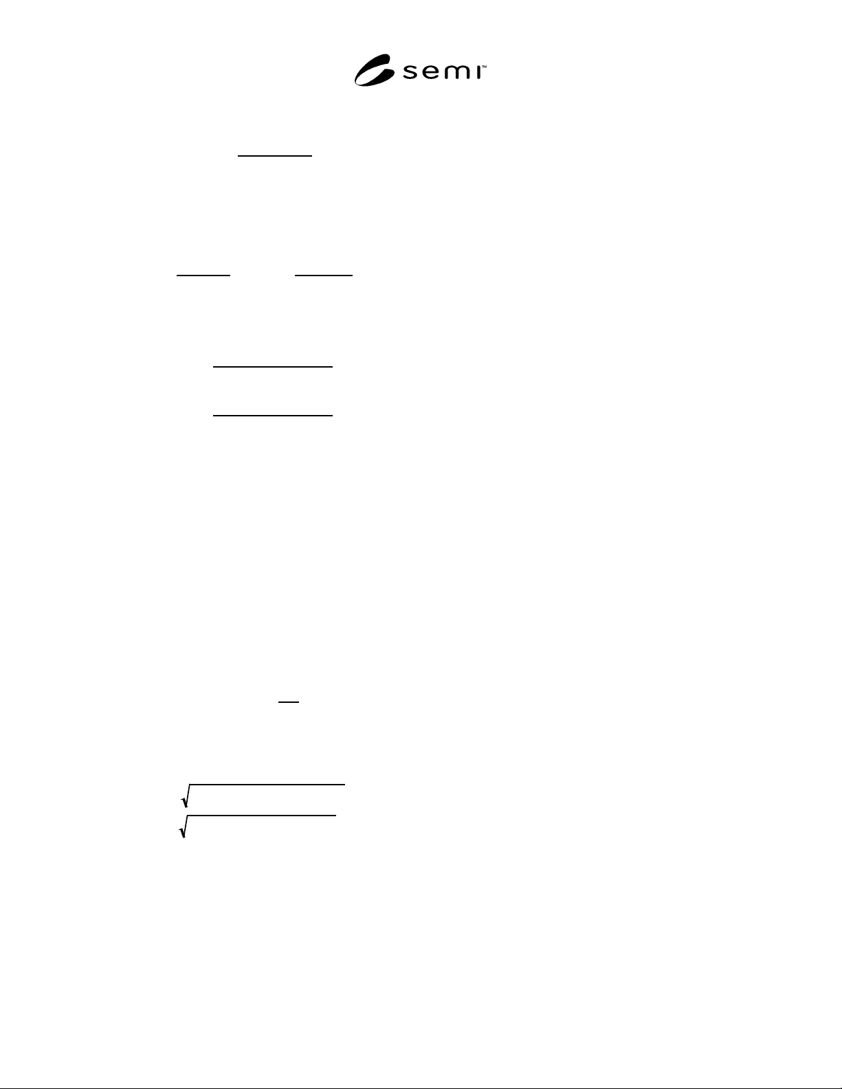
The equipment first calculates Theta, using, for
example, the formula:
Θ=tan
−1
M
A −
M
N
1+ MA MN
where MA and MN are, respectively, the slopes of the
lines connecting the two actual fine sites and the line
connecting the two nominal sites, in “M20”
coordinates, calculated as follows:
MA =
yA
2
− yA
1
xA
2
− xA
1
MN =
yN
2
− yN
1
xN
2
− xN
1
The equipment then calculates DeltaX and DeltaY,
using, for example, the formulas:
DeltaX =
Csin Θ()+ Dcos Θ()
sin Θ()
()
2
+ cos Θ()
()
2
DeltaY =
Csin Θ
()− Dcos Θ()
sin Θ()()
2
+ cos Θ()()
2
where C and D, the adjusted site 1 coordinates in a
rotation-adjusted coordinate system, are calculated,
for example, using the formulas:
C
= yA1 − ((
xN
1 sinΘ ) + ((y
N
1 cosΘ)
D = xA1 − ((xN1 cosΘ) − ((yN1 sinΘ)
The equipment can also calculate a ScaleFactor term
to indicate the relative ratio between the length of the
vector connecting the nominal alignment sites and the
length of the vector connecting the actual alignment
sites. This can be used, for example, to judge whether
there is a problem with the alignment process, since
the difference between these two vectors should be
small.
ScaleFactor =
VA
V
N
where VA and VN are the length of the vectors
connecting the actual and nominal alignment sites,
calculated using the formulas:
VN = yN
2
− yN
1
()
2
+ xN
2
− xN
1
()
2
VA = yA
2
− yA
1
()
2
+ xA
2
− xA
1
()
2
SEMI 30.1-0200 © SEMI 1998, 200045
Figure 7
Review Data Management