semi合集-English.pdf - 第2256页
SEMI E58-0703 © SEMI 1997, 2003 37 RELATED INFORMATION 1 NOTE: This related information is not an o fficial part of SEMI E58 and is not inte nded to modify or supersede the official standard. Rather, these notes are auxi…

SEMI E58-0703 © SEMI 1997, 2003
36
NOTICE: SEMI makes no warranties or representations as to the suitability of the standards set forth herein for any
particular application. The determination of the suitability of the standard is solely the responsibility of the user.
Users are cautioned to refer to manufacturer’s instructions, product labels, product data sheets, and other relevant
literature respecting any materials mentioned herein. These standards are subject to change without notice.
The user’s attention is called to the possibility that compliance with this standard may require use of copyrighted
material or of an invention covered by patent rights. By publication of this standard, SEMI takes no position
respecting the validity of any patent rights or copyrights asserted in connection with any item mentioned in this
standard. Users of this standard are expressly advised that determination of any such patent rights or copyrights, and
the risk of infringement of such rights, are entirely their own responsibility.
SEMI E58-0703 © SEMI 1997, 2003 37
RELATED INFORMATION 1
NOTE: This related information is not an official part of SEMI E58 and is not intended to modify or supersede the official
standard. Rather, these notes are auxiliary information provided as background or examples of possible application and are
included as reference material. The standard should be referred to in all cases. SEMI makes no warranties or representations as to
the suitability of the material set forth herein for any particular application. The determination of the suitability of the material is
solely the responsibility of the user.
This section describes different applications of
ARAMS, including an example of a method for
estimating the time of powerdown as well as various
scenarios.
R1-1 Estimating Powerdown Time
R1-1.1 This section describes a method for estimating
the time at which a loss of power, reset, or re-boot
occurs. Estimation of this time, allows the accumulation
of time-in-state for the previous ARAMS state to be
maintained.
R1-1.1.1 The equipment maintains a date/time value,
PowerdownTime, that is used to estimate the time when
a loss of power occurred (see Section 11.2.12). In this
example, the equipment provides an additional user-
configurable variable, UpdatePeriod, that defines the
number of seconds in an update period. UpdatePeriod is
used to set an interval timer. PowerdownTime is
updated with the current date and time at the end of
each timed interval.
R1-1.1.2 Whenever the equipment enters the
initialization state, whether through powerup, reset, or
re-boot, it uses the value found in PowerdownTime as
the estimate of when the powerdown occurred. If a state
change occurs as the result of a powerdown, then the
time that has elapsed since the point of powerdown is
used to update the appropriate time-in-state
accumulator for the previous ARAMS state.
R1-1.1.3 For an example of the sequence of events and
actions following a powerup, see Section R1-2.
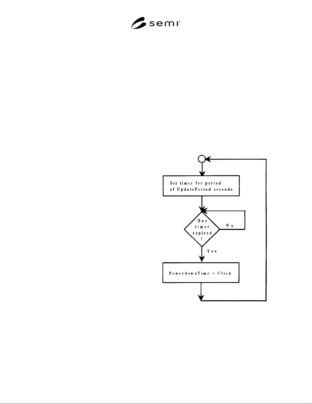
R1-1.1.4 Figure R1-1 provides a simple logic flowchart
as an illustration of the update process.
R1-1.2 UpdatePeriod — The length of the time
interval, in seconds, for updating PowerdownTime.
Form: positive integer.
R1-2 Powerup Scenario
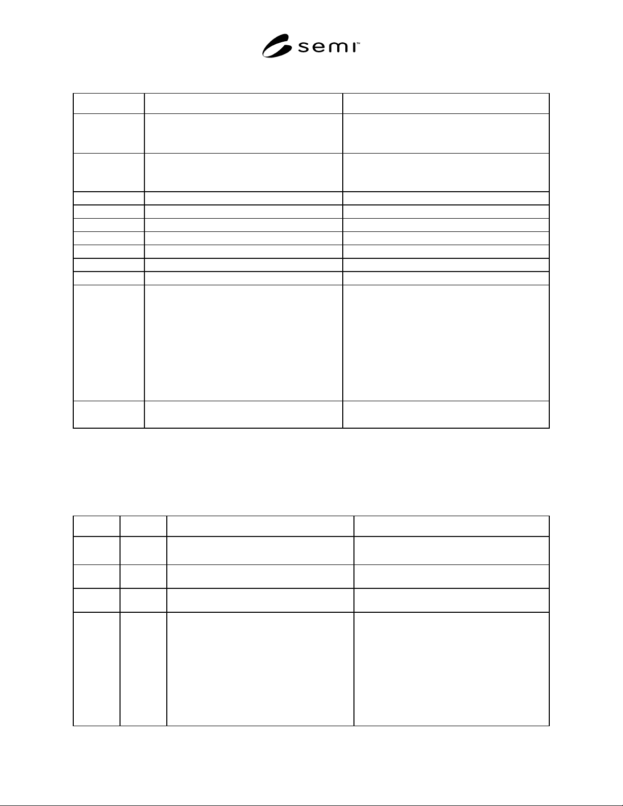
R1-2.1 This scenario is analogous to a timing diagram.
It illustrates the actions that occur at different times in
sequence, showing the effect of a powerdown that
occurs while the equipment was in the PRODUCTIVE
state. In this example, accumulators defined in Section
11.5 are supported. UpdatePeriod is defined in the prior
section and is set to a value of 30 seconds.
R1-2.2 In this example, the equipment received
instructions for processing prior to the start of the
timing and waited briefly for the material to arrive.
Timing shown in this example begins when it receives
the expected material and transitions from
STANDBY to PRODUCTIVE at time = t
0
. After a
sequence of its normal periodic updates (t
i
= t
i-1
+
UpdatePeriod) of the estimated time of powerdown, it
loses power while still in the PRODUCTIVE state.
Following powerup, it determines the new ARAMS
state, sets the required variables, and reports the state
change to the host.
Figure R1-1
Periodic Update Logic
R1-2.3 The notation “=” indicates the value of a
variable, while “:=” is used to indicate the act of setting
a variable to a specific value. The notation “←” is used
to indicate a message sent from equipment to host, and
the notation “→” is used to indicate a message sent
from the host to equipment.
SEMI E58-0703 © SEMI 1997, 2003
38
Table 17 Table R1-1 Powerup Scenario
Time Action Comment
ARAMSState = “2000”
ARAMSTimestamp = t
-1
PrdState = “1100”
Initial conditions prior to t = t
0
:
Equipment is in STANDBY
PRODUCTION substate is “regular”
t
0
ARAMSTimestamp:= Clock
PrevARAMSState:= ARAMSState
ARAMSState:= PrdState
Requirements for PRODUCTIVE are satisfied.
Equipment transitions automatically.
t
1
= t
0
+ 30 PowerdownTime:= Clock Periodic update of estimated powerdown time.
t
2
= t
1
+ 30 PowerdownTime:= Clock Periodic update of estimated powerdown time.
t
3
= t
2
+ 30 PowerdownTime:= Clock Periodic update of estimated powerdown time.
t
4
= t
3
+ 30 PowerdownTime:= Clock Periodic update of estimated powerdown time.
t
5
= t
4
+ 30 PowerdownTime:= Clock Periodic update of estimated powerdown time.
t
6
= t
5
+ 30 PowerdownTime:= Clock Periodic update of estimated powerdown time.
t
7
Powerdown
t
8
LastPowerdown:= PowerdownTime
PowerdownTime:= Clock
Elapsed time before powerdown =
LastPowerdown –
ARAMSTimestamp (t
6
– t
0
)
ARAMSTimestamp:= LastPowerdown (t
6
)
PrevARAMSState:= ARAMSState (“1100”)
ARAMSState:= “5000” (“UDT”)
PrdTime:= PrdTime + elapsed time (t
6
– t
0
)
Powerup: Transition 1
Equipment system initialization
ARAMS housekeeping
Transition complete.
t
9
← ARAMS State Change Event Report “A”
← ARAMS Transition Event Report “B”
Equipment sends event notification to host.
R1-3 Equipment-Initiated Transition
R1-3.1 This scenario illustrates the events and activities that occur as the result of an equipment-initiated transition
from PRODUCTIVE to UNSCHEDULED DOWNTIME, for equipment supporting the accumulators in Section
11.4.
Table 18 Table R1-2 Equipment-Initiated Transition
Comment Host Equipment Comment
ARAMSState = “1100”
(“PRD/Regular Production”)
Initial conditions.
Equipment detects mechanical fault in wafer
handler.
Equipment suspends processing, transitions to
UNSCHEDULED DOWNTIME, and notifies user.
Elapsed time: = Clock − ARAMS
ARAMSTimestamp:= Clock
PrevARAMSState:= ARAMSState (
“1100”)
ARAMSState:= “5000” (“UDT”)
DowntimeAlarm:= alarm/exception identifier
DowntimeAlarmText := alarm/exception
description
DowntimeData:= additional information
Prdtime:= Prdtime + elapsed time