semi合集-English.pdf - 第418页
SEMI E56-1104 © SEMI 1996, 2004 7 12.6.2 The reference ope rating conditions shall be as follows if the downstream pressure is at vacuum: Ambient temperature 23 ± 2°C Gas tempera ture Same as actual ambient Ambient press…
SEMI E56-1104 © SEMI 1996, 2004 6
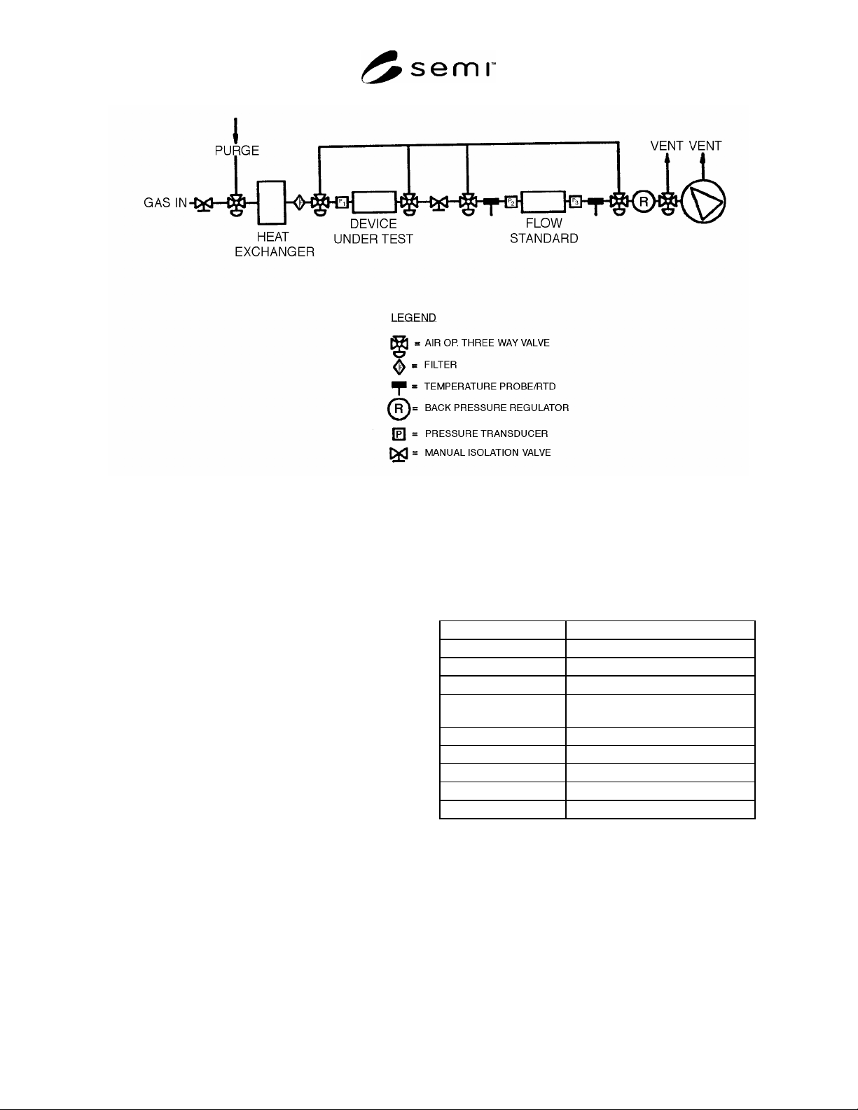
Figure 3
Mass Flow Controller Test Fixture
11 Calibration Standardization
11.1 All measurement devices must have valid
calibration certificates.
12 Conditioning
12.1 Place the MFC to be tested in the testing
environment. Apply power to the MFC for the 24
hours prior to initiating warm-up as defined by the
manufacturer. The valve should be in its “off” position
(closed for a NC valve, open for a NO valve).
12.2 Following the conditioning period, install and
warm up the device according to manufacturer's
specifications.
12.3 Purge the MFC with clean, dry nitrogen or argon
following the warm up period.
12.4 Allow the test gas to flow through the DUT for a
minimum of 10 minutes at 100% of flow.
12.5 Apply a 100% full-scale setpoint to the DUT and
wait for the flow to stabilize for 10 seconds. Apply the
lower setpoint limit to the DUT and wait for the flow to
stabilize for 10 seconds. Repeat this cycle two more
times. This process exercises the device before
initiating the test.
12.6 Test Conditions
12.6.1 The reference operating conditions shall be as
follows if the downstream pressure is atmospheric
pressure:
Ambient temperature 23 ± 2°C
Gas temperature Same as actual ambient
Ambient pressure 101.32 kPa. (+ 4.7 or – 15.3 kPa)
Gas pressure P
1
, Inlet 274 ± 34 kPa
Gas pressure P
3
, Outlet 101.32 kPa. (+ 4.7 kPa or – 15.3
kPa)
Relative humidity 40% ± 10%, noncondensing
Magnetic field 50 µT
Electromagnetic field < 100 µ V/m
Vibration < 0.5 m/s
Shock 3 g

SEMI E56-1104 © SEMI 1996, 2004 7
12.6.2 The reference operating conditions shall be as
follows if the downstream pressure is at vacuum:
Ambient temperature 23 ± 2°C
Gas temperature Same as actual ambient
Ambient pressure 101.32 kPa. (+ 4.7 or – 15.3 kPa)
Gas pressure P1, Inlet 172 ± 34 kPa
Gas pressure P3, Outlet < 0.13 kPa
Relative humidity 40% ± 10%, noncondensing
Magnetic field 50 µT
Electromagnetic field < 100 µ V/m
Vibration < 0.5 m/s
Shock 3 g
12.7 Power Supply Conditions
12.7.1 The reference power supply conditions used
shall be the reference values specified by the
manufacturer. For those instances when a range of
values is specified rather than a reference value, the
midpoint of the range shall be taken to be the reference
value.
12.7.2 The reference power supply must be sufficiently
rated for the DUT. In addition, the following supply
conditions and tolerances shall apply:
DC supply reference voltage ± 0.1% of operating
voltage
Noise and ripple of DC
supply
0.1% rms
13 Procedure
13.1 Zero Offset — Close the gas shut-off valve
upstream of the DUT and apply a 100% setpoint to the
DUT to equilibrate the pressure across the MFC. Wait
for the flow to stabilize at a value near zero; then close
the downstream shut-off valve. Deactivate the MFC’s
control valve (open for (NO) valves, closed for (NC)
valves), and allow the MFC to auto-zero if the an auto-
zero option is available. After the electrical output
signal has stabilized for at least three minutes, record
the MFC zero offset in Table 1. (Consult the
manufacturer’s specifications for the stabilization time
and report this time on Table 2.)
Table 1 Data Tabulation
Input % Set Point (sccm) Indicated Flow (sccm) Actual Flow (sccm)
40 Wait 5 minutes. Record no data.
50
60
70
80
90
100
90
80
70
60
50
40
30
20
10
5
Minimum
#1
5
10
20
30
40
50
60

SEMI E56-1104 © SEMI 1996, 2004 8
Input % Set Point (sccm) Indicated Flow (sccm) Actual Flow (sccm)
70
80
90
100
90
80
70
60
50
40
30
20
10
5
Minimum
#1
5
10
20
30
40
50
60
70
80
90
100
90
80
70
60
50
40
30
20
10
5
Minimum
#1
5
10
20
30
40
50
#1
Per Section 13.5.4.1
#2
Test for accuracy, linearity, repeatability, short-term reproducibility, and hysteresis.