semi合集-English.pdf - 第5123页
SEMI M29-1296 © SEMI 1996, 2003 3 5.2.2 Orientation Mark — The orient ation m ark indicati ng the fr ont side o f a cassette is shown i n Figure 3 and Table 1. This s upports a user t o manually set a cassette on a box b…
SEMI M29-1296 © SEMI 1996, 2003 2
4.1.15 shipping box — a whole container containing a
shipping cassette. This is composed of a shipping
cassette, an outer box, retainers, gasket, and clamps.
4.1.16 shipping cassette — a cassette additionally
defined herein for shipping among cassettes.
4.1.17 stacking rib — a rib formed on a top surface of
a box top and on a bottom surface of a box bottom so as
not to collapse when shipping boxes are stacked. A rib
positioned on the top is called a top rib, and a rib on the
bottom a bottom rib.
4.1.18 supporting rib — a rib inside an outer box for
supporting a cassette.
5 Requirements
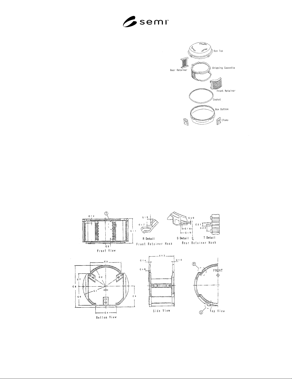
5.1 Part Construction — A shipping box defined
herein is composed of the parts shown in Figure 1.
5.1.1 The appearance of this part is one of
embodiments of this definition.
Figure 1
Components
5.2 Shipping Cassette
5.2.1 Additional Dimensions — Dimensions of a
shipping cassette should conform to SEMI E57 and
SEMI E1.9. However, in the above documents, there
are many Max. or Min. notations, and hence, they are
not sufficient to design a shipping box. Therefore, in
Figure 2 and Table 1, necessary dimensions are added
within the ranges defined in the above documents.
Figure 2
Additional Definition of Shipping Cassette
SEMI M29-1296 © SEMI 1996, 2003 3
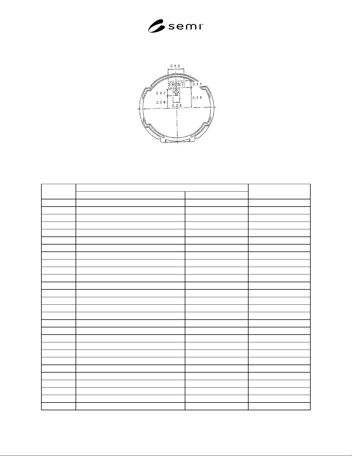
5.2.2 Orientation Mark — The orientation mark indicating the front side of a cassette is shown in Figure 3 and
Table 1. This supports a user to manually set a cassette on a box bottom or a platform of equipment.
Figure 3
Orientation Mark of Shipping Cassette
Table 1 Dimensions of Shipping Cassette
Unit: mm
Standardized Dimension
Location
13 Wafers 25 Wafers
Corresponding to
SEMI E1.9
C1 166 ± 0.5 ← r5
C2 153.5 ± 0.5 ← r6
C3 224 ± 1 ← x6 + x6
C4 152 ± 0.5 ← x5 + x5
C5 155 ± 0.5 ← y16
C6 139.5 ± 0.5 ← y23
C7 94 ± 0.5 ← y15
C8 308.5 ± 1 ← r6 + y16
C9 31 ± 0.5 ← z8 - z1
C10 3 ± 0.5 ←
C11 182 ± 1 302 ± 1.5
C12 29.5 ± 0.5 ← z18
C13 179 ± 3 299 ± 4
C14 10 ± 1 ←
C15 11 ± 1 ←
C16 5 ± 0.5 ←
C17 5 ± 0.5 ←
C18 51 ± 0.5 ← x1
C19 55 ± 0.5 ←
C20 4 ± 0.5 ←
C21 9 ± 0.5 ←
C22 20 ± 0.5 ←
C23 70 ± 10 ←
C24 30 ± 10 ←
C25 90 ± 10 ←
C26 30 ± 10 ←
C27 30 ± 10 ←
C28 55 ± 10 ←
SEMI M29-1296 © SEMI 1996, 2003 4
5.3 Box Top
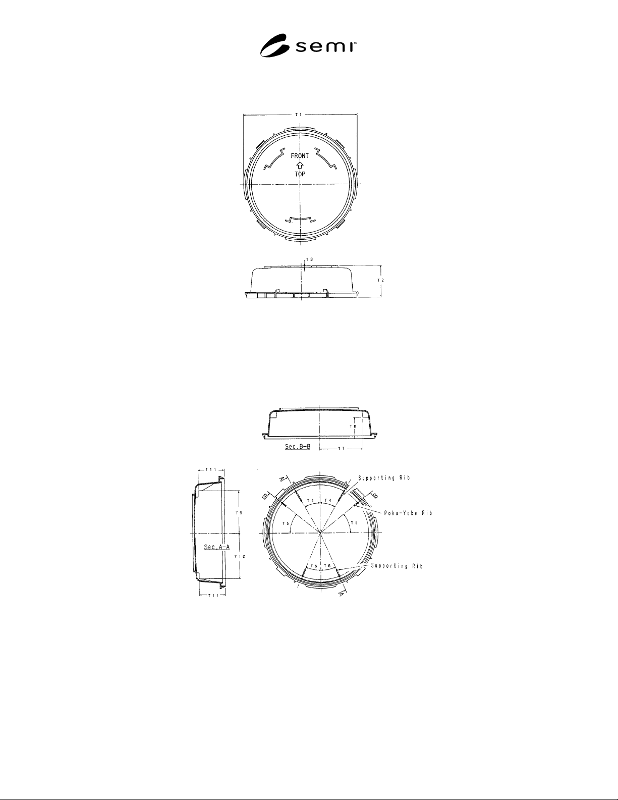
5.3.1 Outer Dimensions — Outer dimensions of a box top are shown in Figure 4 and Table 2.
Figure 4
Outer Dimensions of Box Top
5.3.2 Supporting Rib and Poka-yoke Rib — Positions of a supporting rib for supporting a shipping cassette inside a
box top and a poka-yoke (fool-proof) rib for avoiding setting the box top in a wrong orientation are shown in Figure
5 and Table 2.
Figure 5
Supporting Rib and Poka-yoke Rib of Box Top
5.3.3 Gasket Area — It is required to provide a gasket in an area shown in Figure 6 and Table 2 if the gasket is
provided.
5.3.4 Clamping Indent — Figure 7 and Table 2 show dimensions of a concave part for receiving a clamp. Refer to
Figure 8 and Table 2 for horizontal positions.