semi合集-English.pdf - 第127页
SEMI E17-0600 © SEMI 1991 , 2000 3 Dead Tim e (seco nds) Initia l Set P oin t Tra nsient Und ershoot (% o f Set Point Step Chan ge) Trans ient Ov ershoot ( % of Se t Po int Cha nge) Step Re sponse Ti m e (se conds) Sett …
SEMI E17-0600 © SEMI 1991, 2000 2
the median absolute pressure is considered adequate for
most mass flow controllers.
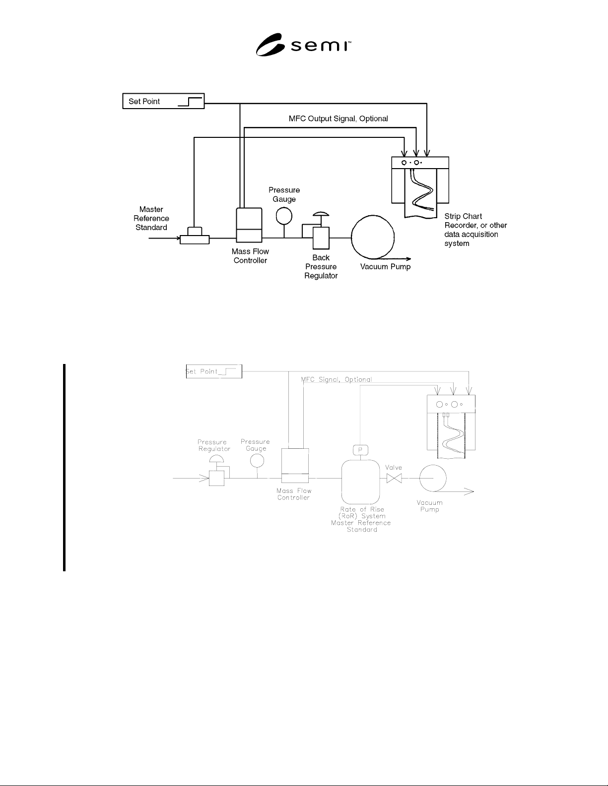
3.5 Nitrogen is the recommended gas for the standard
test shown in Figure 3a. The inlet pressure is 25 psig
(1.75 kg/cm
2
G). Outlet pressure is the prevailing
atmospheric pressure. The temperature of the gas
entering the flow controller and the temperature
surrounding the flow controller shall be the same.
Neither shall vary during the test so as to have a
significant effect.
3.5.1 The preceding conditions are recommendations.
Deviations may be made to more accurately reproduce
the conditions that the MFC will experience in use,
such as the variation shown in Figure 3b. Any deviation
from the above gas and pressure conditions and/or test
setup must be noted with the test results.
3.6 The master reference standard is used to provide a
representation of the instantaneous actual flow. It is
customary to refer to the output of the master reference
standard as the actual flow. It shall have an accuracy of
± 5% of reading (including linearity), or better, over the
flow range for which results will be reported. The
pressure drop across the master reference standard at
the test flow shall be small enough to not effect the
response of the MFC under test.
3.6.1 Typical master reference standards are Hot-Wire
flow meters (or similar immersible thermal flow
sensors), laminar flow elements with a differential
pressure transducer, and Rate of Rise (RoR) systems.
3.7 The measuring system response time is the sum of
the pneumatic time constant, master reference response
time and the recording system response time. The
measuring system response time shall be less than 1/5
of any reported transient characteristic. If the measuring
system response time is greater than 1/5 of a specific
transient characteristic, that characteristic may be
reported if the measuring system response time is also
reported.
3.8 The test setup shall provide a step change in the
setpoint to the mass flow controller, along with a time-
zero cue to the data acquisition system. The step change
transient time shall be less than 1% of the step response
time of the MFC under test.
3.9 The test setup is recommended for MFC full scale
flow rates above 10 sccm. In those cases where the flow
rate is below 10 sccm and the pneumatic time constant
is not less than 1/5 of the step response time of the
MFC the pneumatic time constant shall be reported.
3.10 The MFC shall be electrically energized for the
supplier recommended “warm up” time prior to the start
of the test.
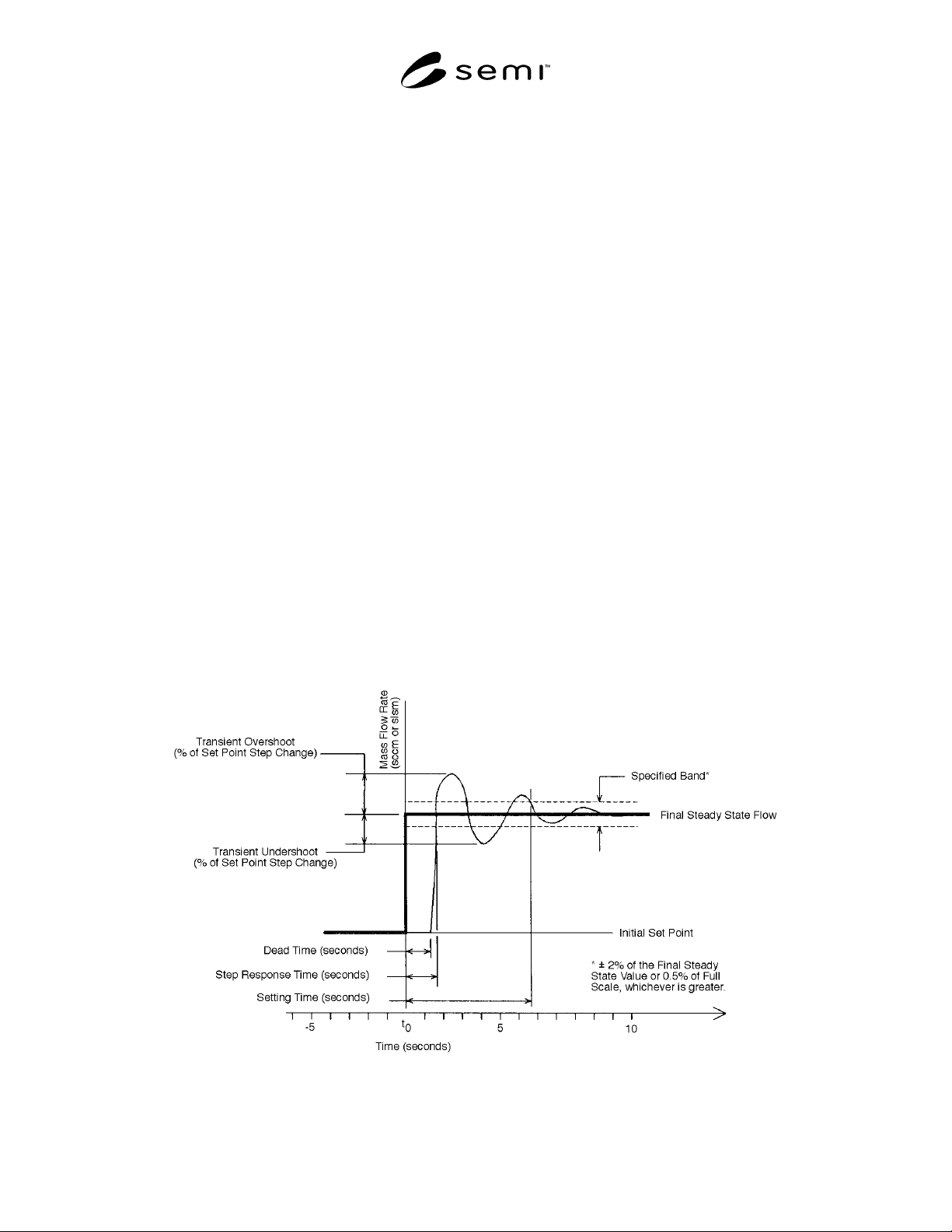
Figure 1
Definitions of MFC Transient Characteristics Terminology in the Case
Where the Final Set Point Is Higher than the Initial Set Point
SEMI E17-0600 © SEMI 1991, 20003
Dead Time (seconds)
Initial Set Point
Transient Undershoot
(% of Set Point Step Change)
Transient Overshoot
(% of Set Point Change)
Step Response Time (seconds)
Settling Time (seconds)
* ± 2% of the Final Steady State Value or
0.5% of Full Scale, whichever is greater
Final Steady State Flow
Specified Band
-5
t
0
5
10
Time (seconds)
Mass Flow Rate
(sccm or slsm)
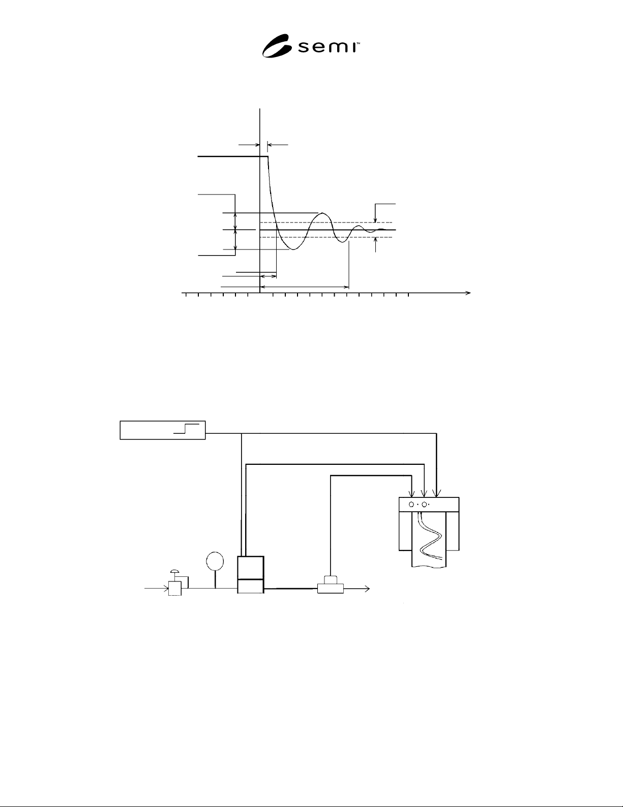
Figure 2
Definitions of MFC Transient Characteristics Terminology in the Case
Where the Final Set Point Is Lower than the Initial Set Point
Set Point
Pressure
Gauge
Pressure
Regulator
Gas Supply
Mass Flow
Controller
Master Reference
Standard
Strip Chart
Recorder, or other
data acquisition
system
MFC Output Signal Optional
Figure 3a
MFC Transient Characteristics Test Setup with Outlet at Atmospheric Pressure
SEMI E17-0600 © SEMI 1991, 2000 4
Figure 3b
MFC Transient Characteristics Test Setup with Outlet at Vacuum
Figure 3c
VFC Transient Characteristics Test Setup with Rate of Rise (RoR) System
4 Test Procedure
4.1 Evaluate the transient characteristics from “OFF” to a flowing condition at final set point by a transition in set
point voltage only.
4.1.1 Apply a set point voltage sufficient to close the control valve following the manufacturer’s recommendation.
This may be a voltage other than zero, either positive or negative. Allow the output of the mass flow controller and
the actual flow, if any, to stabilize.
4.1.2 Apply the final set point value as shown in Table 1.