semi合集-English.pdf - 第290页
SEMI E47.1-0305 © SEMI 1997, 2005 5 z 67 79.5 z 66 55.5 z 68 133.5 (253.5) z 69 157.5 (277.5) y 60 155 faci al datum pl ane horizontal datum plane of FO UP nest or load p ort hori zontal datum pl ane insi de FO…
SEMI E47.1-0305 © SEMI 1997, 2005 4
6.3 Interior Dimensions — The interior of the FOUP must have the interior dimensions of the cassette specified in
SEMI E1.9. Many of these dimensions are measured from a horizontal datum plane, so an internal horizontal datum
plane is still specified to be z44 above the horizontal datum plane under the FOUP.
6.4 Door
6.4.1 (This section (6.4.1) is no longer applicable, and is intentionally left blank so as to maintain paragraph
numbering.)
6.4.2 , The FOUP door is on the front side of the FOUP (corresponding to the front side of the cassette where
wafers are accessed so the door is perpendicular to the wafers and parallel to the facial datum plane), and the door
and its frame must be designed to mate with a port that conforms to SEMI E62. Specifically, the FOUP door and its
frame must have surfaces that mate with the seal zones and the reserved spaces for vacuum application (which
includes all of the circles bounded by r38 except for the holes for the registration pins at the center of each circle)
defined in ¶¶5.3 and 5.6 of SEMI E62 (which specifies r38). These FOUP door and frame surfaces must be a
distance of y52 from the facial datum plane and must have a flatness of y42. No surface on the FOUP door may
project further from the facial datum plane than the door seal zone and the reserved spaces for vacuum application.
The door of the FOUP must also be designed so that when the FOUP is pressed against the FIMS port, both latch
keys on the port are inserted to their full length. Furthermore, when the latch keys are turned more than 45° toward
the position that unlocks the FOUP door from the FOUP, the latch key holes on the door must be such that the door
is not removable from the latch keys.
6.5 Wafer Capture and Centering — When the FOUP is closed, the wafers must be captured in the FOUP to
prevent movement during transport. Wafer capture must include gently pushing the wafers to the rear of the cassette
to center them.
6.6 Internal Dimensions —The interior of any FOUP must not intrude on the end effector exclusion zone, and the
inside of the door must not intrude more that y51 toward the facial datum plane. The interior of the FOUP between
y11 and the door opening must not protrude higher than z6 above the internal horizontal datum plane and lower than
z15 above the top nominal wafer plane. Horizontally, it must not protrude closer to the bilateral datum plane than
x51 between y11 and y49 or closer than x52 between y49 and y52 (as shown in Figure 10). Dimensions x51, x52,
y49, and y52 are specified in Table 1, and y11, z6, and
z15 are specified in SEMI E1.9.
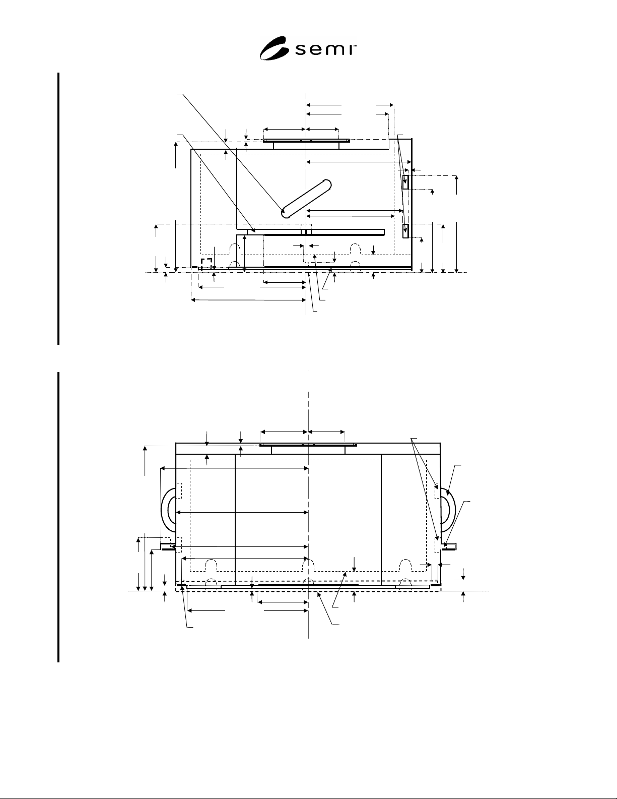
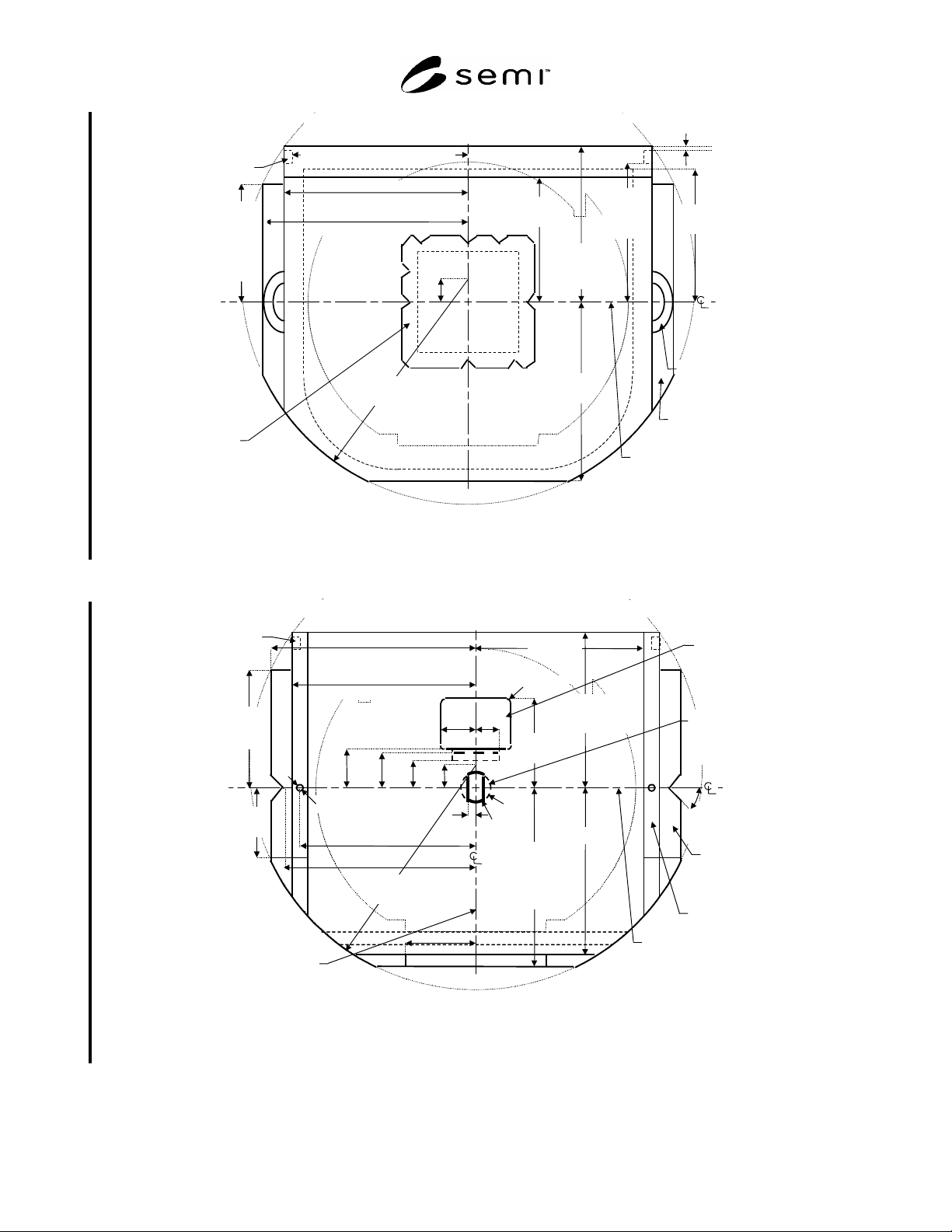
6.7 External Dimensions — Figures 5 through 8 show the side view, rear view, top view, and bottom view for the
FOUP. Table 1 defines all of the dimensions. In this and following figures, the heaviest lines are used for surfaces
that have tolerances (not surfaces that have only maximum or only minimum dimensions). If a FOUP identification
tag is used, it must be located at the bottom rear centered on the bilateral datum plane and must be contained within
the maximum outer dimensions of the FOUP.
NOTE 1: Figures 1 through 4 have been removed from this document.
SEMI E47.1-0305 © SEMI 1997, 2005 5
z
67
79.5
z
66
55.5
z
68
133.5
(253.5)
z
69
157.5
(277.5)
y
60
155
facial
datum plane
horizontal datum plane of FOUP nest or load port
horizontal datum plane inside FOUP
z
41
0
y
53
190
y
56 =189.75±0.25
(at bottom rail)
bottom conveyor rail
z
43 =2±1
y
58
75
y
50
130
y
51
140
z
44 =11±0
(numbers in parentheses are for 25-wafer FOUPs, if different)
y
57
178
y
46
=71±1
y
44
53
z
49
8
z
48
15
z
47
=210
(330)
±1
y
52 =165.5±0.5
(at seal zones, etc.)
166 (elsewhere)
d
65
=10±0.5
z
65
7
z
46
=60±1
z
59
72
human
handle
(optional)
side
fork-lift
flange
(optional)
y
61 =3.5±0.5
front clamp features
y
40 =122.5±2.5
Figure 5
Side View of FOUP
z
59
72
human
handle
(optional)
side
fork-
lift
flange
(optional)
bilateral datum plane
z
41
0
x
57
180
(numbers in parentheses are for 25-wafer FOUPs, if different)
z
43 =2±1
z
44
=11±0
horizontal datum plane
of FOUP nest or load port
horizontal datum plane inside FOUP
bottom conveyor rail
x
50 =214±1
(at side fork-lift flange)
x
56 =194.75
±0.25
(at bottom rail)
x
53
195
(elsewhere)
x
46
=71±1
x
44
53
z
49
8
z
48
15
z
47
=210
(330)
±1
x
58
75
d
65 =10±0.5
z
65
7
x
65 =187.5
z
46
=60±1
x
63 =199.3±1
front clamp feature
s
Figure 6
Rear View of FOUP
SEMI E47.1-0305 © SEMI 1997, 2005 6
y
52 =165.5±0.5
(at seal zones,
etc.)
166
(elsewhere)
x
62
188.5 (front clamp flange)
y
53
190
robotic
handling
flange
(see
Figure
12)
bilateral
datum plane
front side of the cassette and FOUP where wafers are accessed
y
51
140
y
50
130
x
61
190.5 (front clamp flange)
x
53
195 (elsewhere)
x
50
215 (at side fork-lift flange
and human handle)
human
handle
(optional)
side fork-
lift flange
(optional)
y
67
=25
r
67
240
facial
datum
plane
y
40
=122.5
±2.5
(to side
fork-lift
flange)
y
61 =3.5±0.5
y
60
155
(to front
clamp
feature)
front clamp
feature
Figure 7
Top View of FOUP
y
40
=122.5
±2.5
facial
datum
plane
bottom
conveyor rail
center
retain-
ing
feature
side
fork-lift
flange
(optional)
y
62
28
x
50 =214±1
(at side fork-lift flange)
x
56 =194.75 ±0.25
(at bottom rail)
x
53
195 (elsewhere)
y
52 =165.5±0.5
(at seal zones, etc.)
166 (elsewhere)
r
60 =16
±0.5
r
64
9.5
x
64
35
y
58
75
bilateral
datum
plane
x
y
53
190
y
56
=189.75±0.25
(at rear
conveyor rail)
y
57
178
front side of the cassette and/or FOUP where wafers are accessed
y
65
104
x
60
=8.0±0.5
r
61
16
front
retaining
feature
x
58
75
y
67
=25
r
67
240
y
64
=42.1
±0.5
y
63
=37.3
±0.5
d
65 =10±0.5
x
65 =187.5
x
68
25
x
63 =199.3±1
(4x)
=45
±0.5°
front clamp
feature
57
180
Figure 8
Bottom View of FOUP