semi合集-English.pdf - 第2849页
SEMI E102-0600 © SEMI 2000 57 RELATED INFORM A TI ON 2 LOGICA L P A RTITION STORA GE NOT E: This re lated informa tion is not an official pa rt of SEMI E10 # and w as derive d from the w ork of the I300I /J30 0E AMHS wor…
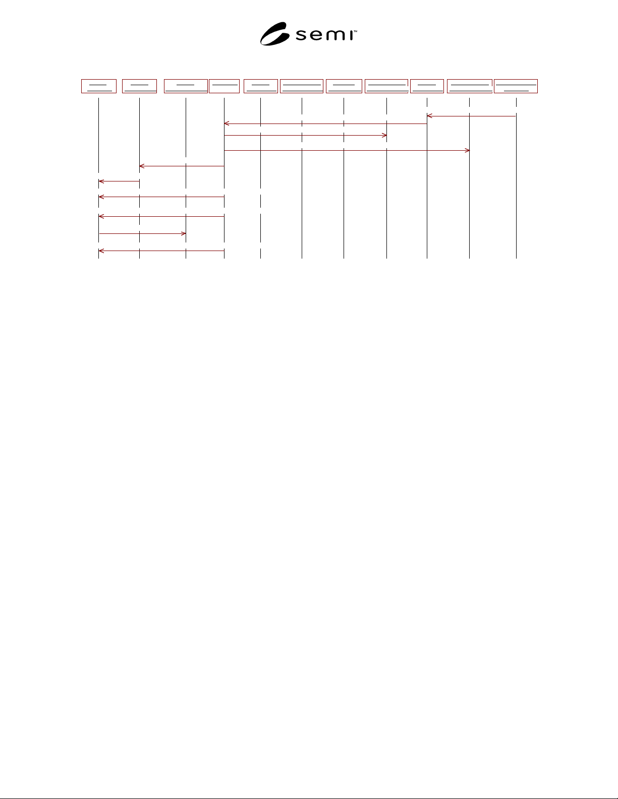
SEMI E102-0600 © SEMI 2000 56
Factory
Operations
Material
Container aaa
Material
TransportManager
Job TrJob1 AMHS Equipment
Controllers
MaterialTracking
Location ohs2MTL
MaterialTracking
Location stk4MTL
MaterialTracking
Location stk9MTL1
Storage
Machine stk9
Transport
Machine Ohs2
Storage
Machine stk4
36: makeInTransit()
37: MaterialContainerStateChangedEvent
39: informJobStateChange(Job TrJob1, previousState JobExecuting, newState JobCompleted)
34: removeMaterial(MaterialContainer aaa)
35: addMaterialToTrack(MaterialContainer aaa)
38: JobStateChangedEvent(..previousState JobExecuting, newState JobCompleted)
40: removeFinishedJob(Job TrJob1)
41: JobStateChangedEvent(..previousState JobCompleted, newState JobUndefined)
32: Transfer Command Complete (Stocker SEM)
33: Transfer Command Complete (Internal Interface)
Figure R1-27
Scenario Case 13 (continued)
SEMI E102-0600 © SEMI 200057
RELATED INFORMATION 2
LOGICAL PARTITION STORAGE
NOTE: This related information is not an official part of SEMI E10# and was derived from the work of the I300I/J300E AMHS
workgroup accomplished during development of the proposed standard. This related information is included with the Material
Transport and Storage Component specification to aid the readers in understanding the intent and use of the standard. This related
information was approved for publication by full letter ballot procedures on January 14, 2000.
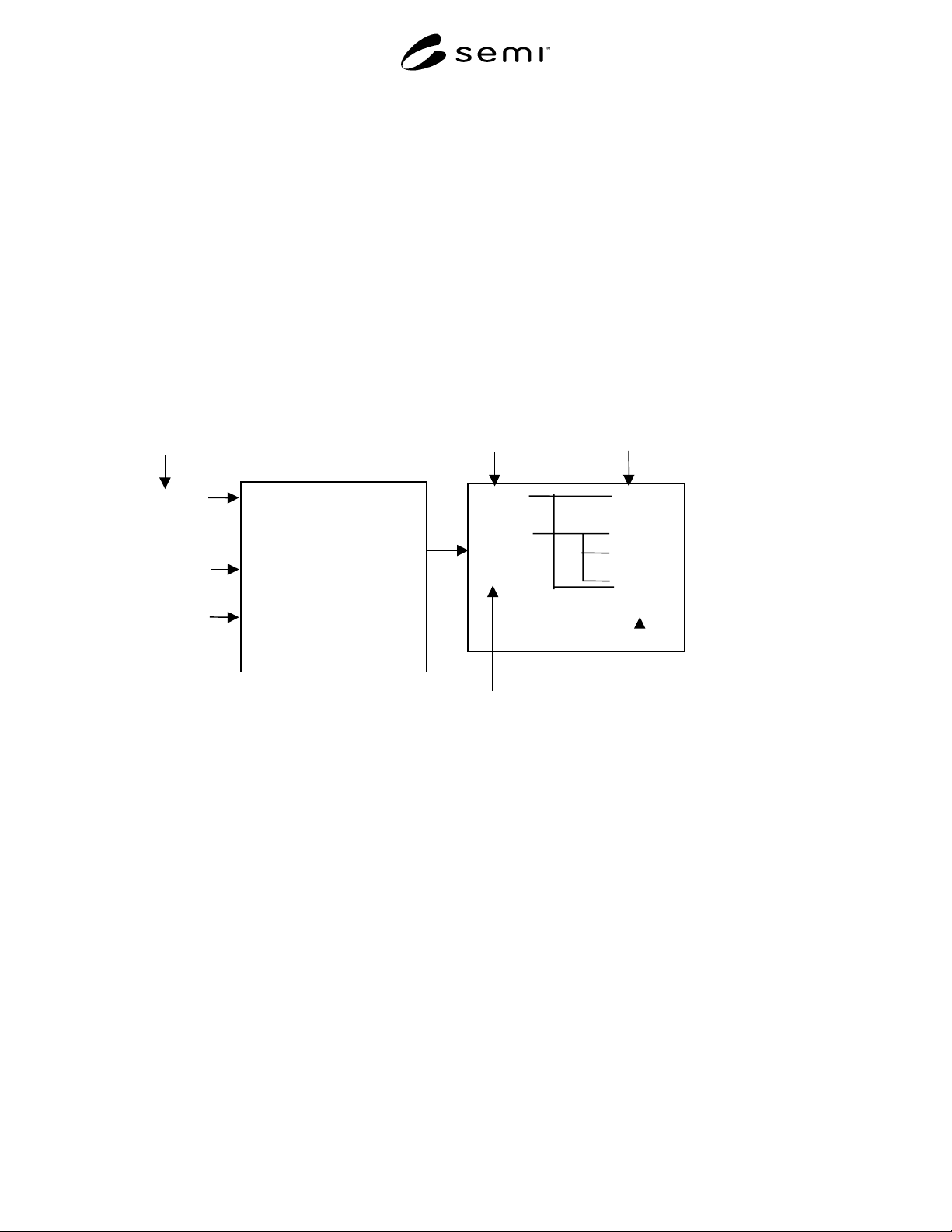
R2-1 The concept of Stocker storage via logical partitions has been implemented through the use of the
MaterialTrackingLocation concept and interfaces. In the example below, the correlation between Durables and
MaterialTrackingLocations are each object’s unit attribute. First, the Factory Supervisor sets the Durable unit to a
particular value based on user specifications. The MTSC then maps the Durable Unit to the appropriate
MaterialTrackingLocation unit for the destination Storage Machine in order to determine the appropriate logical
partition for that particular durable. It is not required that the Durable unit and MaterialTrackingLocation unit be
identical in order for a mapping to occur, the MTSC may implement mapping logic in order to obtain various
relationships between Durable units and MaterialTrackingLocation units.
<Factory Supervisor>
Factory Supervisor determines
the “Parameter ” based on the
rules.
Factory Supervisor writes the
“Unitvalue ” using “setUnit”
for the carrier.
<MTSC>
MTSC maps durable unit to
machine MTL unit.
Photo
Dummy
Empty
Durable Units Machine MTL Units
Product
Flow
Type of Carrier
Durable unit to
Machine MTL
unit mapping
Conditions
MTM obtains “Durable Units” using
“getUnit” from Durable interface.
L/P-1
L/P-2
L/P-3
L/P-4
L/P-5
L/P-6
L/P-7
MTM obtains “Machine MTL Units” using
“getUnit” from Machine MTL interface.
Figure R2-1
Storage in Logical Partitions
NOTICE: SEMI makes no warranties or representations as to the suitability of the specification set forth herein for
any particular application. The determination of the suitability of the specification is solely the responsibility of the
user. Users are cautioned to refer to manufacturer’s instructions, product labels, product data sheets, and other rele-
vant literature respecting any materials mentioned herein. These specifications are subject to change without notice.
The user’s attention is called to the possibility that compliance with this specification may require use of
copyrighted material or of an invention covered by patent rights. By publication of this specification, SEMI takes
no position respecting the validity of any patent rights or copyrights asserted in connection with any item mentioned
in this specification. Users of this specification are expressly advised that determination of any such patent rights or
copyrights, and the risk of infringement of such rights, are entirely their own responsibility.
Copyright by SEMI® (Semiconductor Equipment and Materials
International), 3081 Zanker Road, San Jose, CA 95134. Reproduction o
f
the contents in whole or in part is forbidden without express written
consent of SEMI.

SEMI E105-0701 © SEMI 2000, 20011
SEMI E105-0701
PROVISIONAL SPECIFICATION FOR CIM FRAMEWORK SCHEDULING
COMPONENT
This specification was technically approved by the Global Information & Control Committee and is the direct
responsibility of the North American Information & Control Committee. Current edition approved by the
Japanese Regional Standards Committee on February 1, 2001. Initially available at www.semi.org April
2001; to be published July 2001. Originally published October 2000.
1 Purpose
1.1 The Scheduling Component supports Factory
Operations, Material Transport and Storage, Production
Machine, and Equipment Tracking and Maintenance
components by ordering, in time, jobs that process
material on equipment, move material, and maintain
equipment. The scheduler uses knowledge of product
demand, equipment and material state, process flows,
throughput bottlenecks, operational policy and
constraints, and other information to recommend jobs
that maximize effective utilization of factory resources
to satisfy product demand and planned objectives.
1.2 Increased control over operations requires an
active Scheduling Component that can respond to
factory events and changes in state and dynamically
adjust the schedules for material processing, material
transport and equipment maintenance. The Scheduling
Component can react to inventory levels of material in
the factory to adjust priorities to minimize queue sizes
and ensure that use of bottleneck equipment is opti-
mized to keep WIP inventory levels at desired levels.
1.3 The Scheduling Component can minimize turn
around time (TAT) by coordinating material transport
(for substrates and durables) with processing to reduce
equipment idle time. The Scheduling Component can
sequence activities to minimize setup time. It can also
respond to scheduled and unscheduled equipment
down-time to minimize impact on turn around time. In
addition to minimizing overall TAT, it can react to the
priorities for urgent lots to move them through the
process flow in the minimum possible time while
adjusting the schedules of lower-priority lots that are
impacted.
2 Scope
2.1 The primary run-time responsibilities of the
Scheduling Component are to monitor resource and
material state and apply scheduling and dispatching
decision mechanisms to identify the next activity
(dispatching) or sequence of activities (scheduling) for
factory resources. The Scheduling Component includes
an interface that supports both scheduling and
dispatching. Figure 1 illustrates the interactions
between the Scheduling Component and other
components of the CIM Framework. This illustration
does not reflect all of the many inputs to the Scheduling
Component that are required to provide it with the
current status of the factory resources.
2.2 As described in this standard, the Scheduling
Component produces activity option and activity
forecast lists. These lists are produced by combining
the factory model and status information from other
components with scheduling policies in the Scheduling
Component. For example, the Scheduling Component
combines data from the Specification Component on
how products are made with status data from the
Equipment and Product Management Components to
give activity options for a machine.
2.3 The Factory Operations Component uses the
Scheduling Component services to orchestrate the man-
agement of machines and production of lots. For exam-
ple, when a tool becomes available, Factory Operations
uses the Activity Options list to select the next lot to
process on the tool. Factory Operations then works
with other components to execute the production job for
the lot on the machine. Executing the production job
changes the state of lot and tool in other components.
These status changes are then used by the Scheduling
Component when it produces new activity lists.
2.4 The Scheduling Manager supp orts Factory
Operations by providing an answer to questions like,
“What is next for this material or resource?” The
answer may be based on evaluation of current or future
constraints and objectives. Although the dispatcher's
output takes the form of a decision for the next activity
for the target resource, the interface may also support
manual scenarios by providing a list of prioritized
activities from which the decision is selected.
2.5 The Scheduling Manager interface also provides
forecasts of future activities projected to occur after the
next activity. By simulating anticipated future activity
sequencing and execution timing the scheduler can
generate forecasts that predict future responses from the
dispatcher for subsequent requests. These forecasts are
subject to change as factory conditions change, but they
offer the best current projection of future activity
decisions.