semi合集-English.pdf - 第3657页
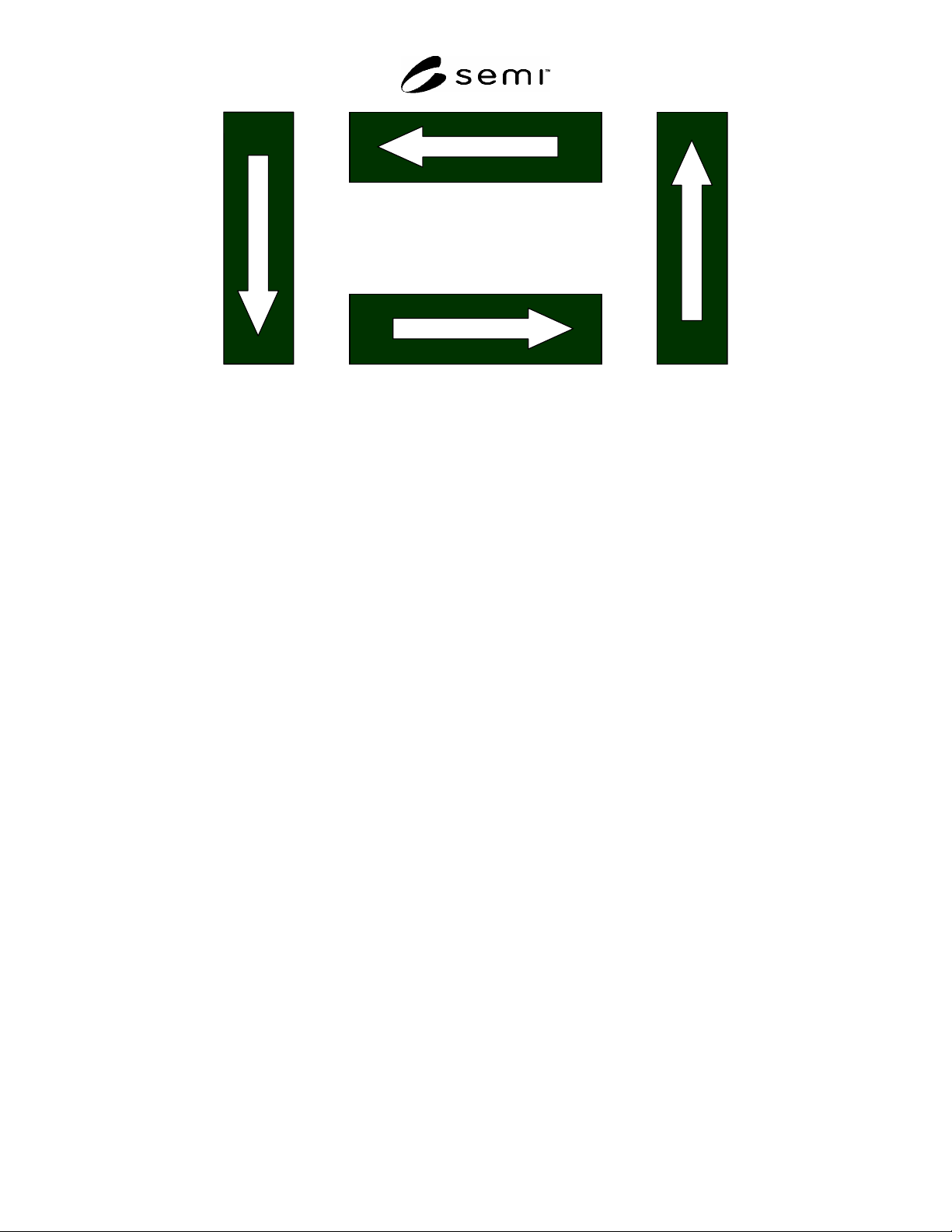
SEMI E142-0705 © SEMI 2005 19 180 Deg. 0 Deg. 270 Deg. 90 Deg. Figure A2-1 Strip Orientation
SEMI E142-0705 © SEMI 2005 18
APPENDIX 2
STRIP MAP
NOTICE: The material in this appendix is an official part of SEMI E142 and was approved by full letter ballot
procedures on December 10, 2004.
A2-1 This appendix shows how the map data items may be applied to strips as well as some additional information
specific to this substrate type.
A2-2 The StripID shall follow the SEMI T9 specification, when applicable, or may be user definable by the factory.
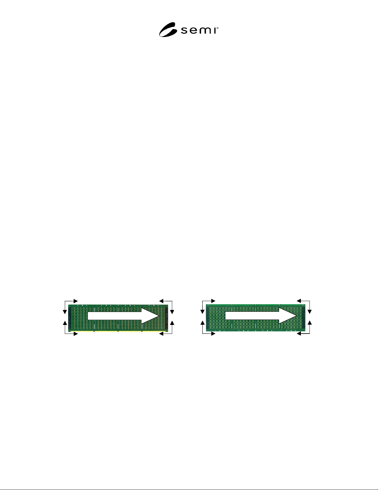
A2-3 For any given process there must be a way to ensure correct orientation of the strip. The end user is
responsible for providing a master manufacturing drawing showing the top side of the strip. This drawing must show
any special markings or patterns that are needed to reliably flip and rotate a physical strip until it is oriented the
same as the drawing. Figure A2-1 defines what is meant by top side and hence bottom side. It also defines what is
meant by upper, lower and left and right.
A2-4 Each strip type will have a factory defined value for OriginLocation. This is the origin reference for the row 1,
column 1 location on the strip. The factory origin, OriginLocation is selected as one of four corners by the factory
host system. The row and column index will be referenced from the selected reference. This information will be
provided to the equipment by the host in each strip map download scenario.
1 = Upper right (UR) top side
2 = Upper left (UL) top side
3 = Lower left (LL) top side
4 = Lower right (LR) top side
6 = Upper right (UR) bottom side
7 = Upper left (UL) bottom side
8 = Lower left (LL) bottom side
9 = Lower right (LR) bottom side
Y Y
X
-Y -Y
X -X
-X
Std Process Direction
1 2
3 4
Top Side
Y Y
X
-Y -Y
X -X
-X
Std Process Direction
6 7
8 9
Bottom Side
Figure A2-1
Strip OriginLocation
SEMI E142-0705 © SEMI 2005 19
180 Deg.
0 Deg.
270 Deg. 90 Deg.
Figure A2-1
Strip Orientation
SEMI E142-0705 © SEMI 2005 20
APPENDIX 3
TRAY MAP ORIENTATION
NOTICE: The material in this appendix is an official part of SEMI E142 and was approved by full letter ballot
procedures on December 10, 2004.
A3-1 This appendix shows how the map data items may be applied to JEDEC trays as well as some additional
information specific to this substrate type.
A3-2 The X-axis (Column) is assigned to the long axis of the JEDEC tray; the Y-axis (Row) is assigned to the short
axis of the tray. This corresponds to Cartesian coordinate “1”. For the origin of the tray, the pocket nearest the bevel
(at the bottom left corner of the tray in Figure A3-1 below) is defined as coordinate location 0,0. (Row/Column).
A3-3 The following values for OriginLocation apply to the JEDEC tray:
1 = Upper right (UR) top side
2 = Upper left (UL) top side
3 = Lower left (LL) top side
4 = Lower right (LR) top side
X
-Y
Y
-Y
Y
-X
X -X
Upper right top side
Lower right top side
Upper left top side
Lower left top side
Figure A3-1
OriginLocation
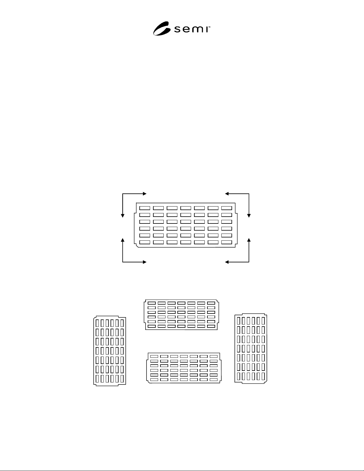
180 Deg.
270 Deg.
90 Deg.
0 Deg.
Figure A3-2
Tray Orientation