semi合集-English.pdf - 第6540页
SEMI G82-0301 E © SEMI 2001 2 7 Requirements 7.1 T he dimens io nal requiremen ts for the load port are given in Table 1 w ith reference to the figures o f th is doc ument. Although the frame cassett e transp ort sy stem…

SEMI G82-0301
E
© SEMI 2001 1
SEMI G82-0301
E
PROVISIONAL SPECIFICATION FOR 300 mm LOAD PORT FOR
FRAME CASSETTES IN BACKEND PROCESS
This specification was technically approved by the Global Assembly & Packaging Committee and is the
direct responsibility of the Japanese Packaging Committee. Current edition approved by the Japanese
Regional Standards Committee on December 1, 2000. Initially available at www.semi.org December 2001,
to be published March 2002.
E
This document was editorially modified in November 2001 to correct a cosmetic error. Changes were made
to Figure 2.
1 Purpose
1.1 This specification defines dimensional
requirements for the load port of frame cassette for 300
mm wafer in backend process equipment. It is intended
to promote a uniform physical interface between
equipment and the factory, to facilitate the use of
automated frame cassette transport systems, and/or to
meet ergonomic requirements for manually loaded
equipment.
2 Scope
2.1 This is a provisional standard covering equipment
for 300 mm frame cassette only. The provisional status
is dictated by the immaturity of designs for 300 mm
equipment and additional specifications which are not
defined yet.
2.2 These standards do not purport to address safety
issues, if any, associated with their use. It is the
responsibility of the user of these standards to establish
appropriate safety and health practices and determine
the applicability of regulatory limitations prior to use.
3 Limitations
3.1 This standard is not intended for use in backend
except frame cassette for 300 mm wafers. This standard
does not address direct loading/unloading of vacuum
load locks. Requirements of such interfaces may differ
from those in this document.
4 Referenced Standards
4.1 SEMI Standards
SEMI E15 — Specification for Tool Load Port
SEMI E15.1 — Specification for 300 mm Load Port
SEMI E57 — Mechanical Specification for kinematic
Couplings Used to Align and Support 300 mm Wafer
Carriers
SEMI E64 — Specification for 300 mm Cart to SEMI
E15.1 Docking Interface Port
SEMI G77 — Specification for Frame Cassette for 300
mm Wafers
5 Terminology
5.1 Please see SEMI G77 for definitions of the
following terms used in this specification:
5.1.1 bilateral datum plane
5.1.2 conveyor rails
5.1.3 facial datum plane
5.1.4 frame cassette
5.1.5 horizontal datum plane
5.1.6 tape frame
5.2 Please see SEMI E15 for definitions of the
following terms used in this specification:
5.2.1 load depth
5.2.2 load face plane
5.2.3 load height
5.2.4 load port
5.2.5 spacing
5.2.6 tool
5.3 frame cassette centroid — a datum representing the
theoretical location of the center of a stack of tape
frames in the frame cassette.
6 Ordering Information
6.1 The following items require communication
between the tool supplier and user and shall be included
in any request for quotation or purchase order:
6.1.1 If the tool has multiple load ports, provide the
spacing, S, between frame cassette centroids (see SEMI
E15).
6.1.2 Specify what frame cassette (e.g. optional
composition, see SEMI G77) is to be accommodated by
the load port (see SEMI E15).

SEMI G82-0301
E
© SEMI 2001 2
7 Requirements
7.1 The dimensional requirements for the load port are
given in Table 1 with reference to the figures of this
document. Although the frame cassette transport
systems shown in these figures appear similar to
overhead monorails, they are intended to represent any
type of transport system (AGV, PGV, conveyor,
overhead track, etc.).
7.2 The dimensional requirements for the placement of
the frame cassette on the load port are given in Table 1
with reference to the figures of this document.
7.3 The tape frames are to be oriented horizontally at
the time they are placed on the load port.
7.3.1 The frame cassette shall be loaded and unloaded
with its front parallel to and away from the load face
plane (see Figure 1).
7.4 Dimension H is nominally 900 mm, fully
adjustable at installation over the range of 890 to 910
mm. The precision with which the load port height
must be maintained is dictated by the needs of the
frame cassette delivery system.
7.5 The load port must nominally be at 900 mm, and it
must be open from above to facilitate automatic frame
cassette delivery from an overhead transport system.
The open volume required for vertical delivery is
defined by a projection of the load port area, including
the area required for C1 and C2 clearances, projected
upward to the top of the tool. Note that this condition
need only be met when the tool is being loaded. For
example, the load port may be formed by a surface that
extends outward during loading to provide overhead
access.
7.6 As shown in Figure 2, the maximum allowable
height of an obstruction on the load port over which the
frame cassette must be lifted (before being set down on
the kinematic couplings) is H1. Examples of such
obstructions include alignment devices and
identification tag readers as well as the kinematic
couplings themselves. Below H1 above the horizontal
datum plane, clearances C1 and C2 no longer apply.
7.6.1 Two exclusion volumes on the left and right side
of the load port must also be kept clear so that fork lifts
or conveyors may be used. Each exclusion volume
extends from the load face plane to D0 beyond the
facial datum plane and extends H0 below the horizontal
datum plane between W1 and W2 from the bilateral
datum plane.
7.6.2 The load port that advances the frame cassette
from the undocked position (where the frame cassette is
initially delivered to the load port) to the docked
position (where the frame cassette is ready for frame
extraction or insertion) must reserve an exclusion
volume that is intended for (but not limited to)
containing automated units that read or write to an ID
tag on the rear of the frame cassette in the undocked
position (where the frame cassette is initially delivered
to the load port). If no reader/writer unit is installed,
the exclusion volume may be covered by a panel.
NOTE 1: This section is incomplete and requirements will be
added to the standard once the requirements and dimensions
have been fully defined.
7.7 Clearances C1 and C2 are defined with respect to
the maximum dimensions of the frame cassette (see
SEMI G77). To prevent interference with overhead
transport systems on the same or adjacent load port, it is
recommended that floor-based transport vehicles do not
exceed clearances C1 and C2 when picking up or
placing the frame cassette on the load port.
7.8 Dimension S specifies the recommended minimum
spacing between frame cassette centroids. In any case,
if S violates C1, then C1 takes precedence.
7.9 To add clearance for overhead frame cassette
transport, no part of the tool in front of the plane
defined by C2 may be higher than H2 from the floor.
The volume below H2 may contain the frame cassette
stored in an internal buffer by the tool.
7.10 The load port must provide the option to use the
conveyor rails for frame cassette loading. At the time
of frame cassette transfer, the conveyor rails must be
positioned at HC3 as shown in Figure 2. When not in
use, the conveyor rails must be lowered below the fork
lift exclusion zone.
8 Related Documents
SEMI E1.9 — Provisional Mechanical Specification for
Cassettes Used to Transport and Store 300 mm Wafers
SEMI E47.1 — Provisional Mechanical Specification
for Boxes and Pods Used to Transport and Store 300
mm Wafers
SEMI E72 — Specification and Guide for 300 mm
Equipment Footprint, Height, and Weight
SEMI G74 — Specification for Tape Frame for 300
mm Wafers
SEMI G82-0301
E
© SEMI 2001 3
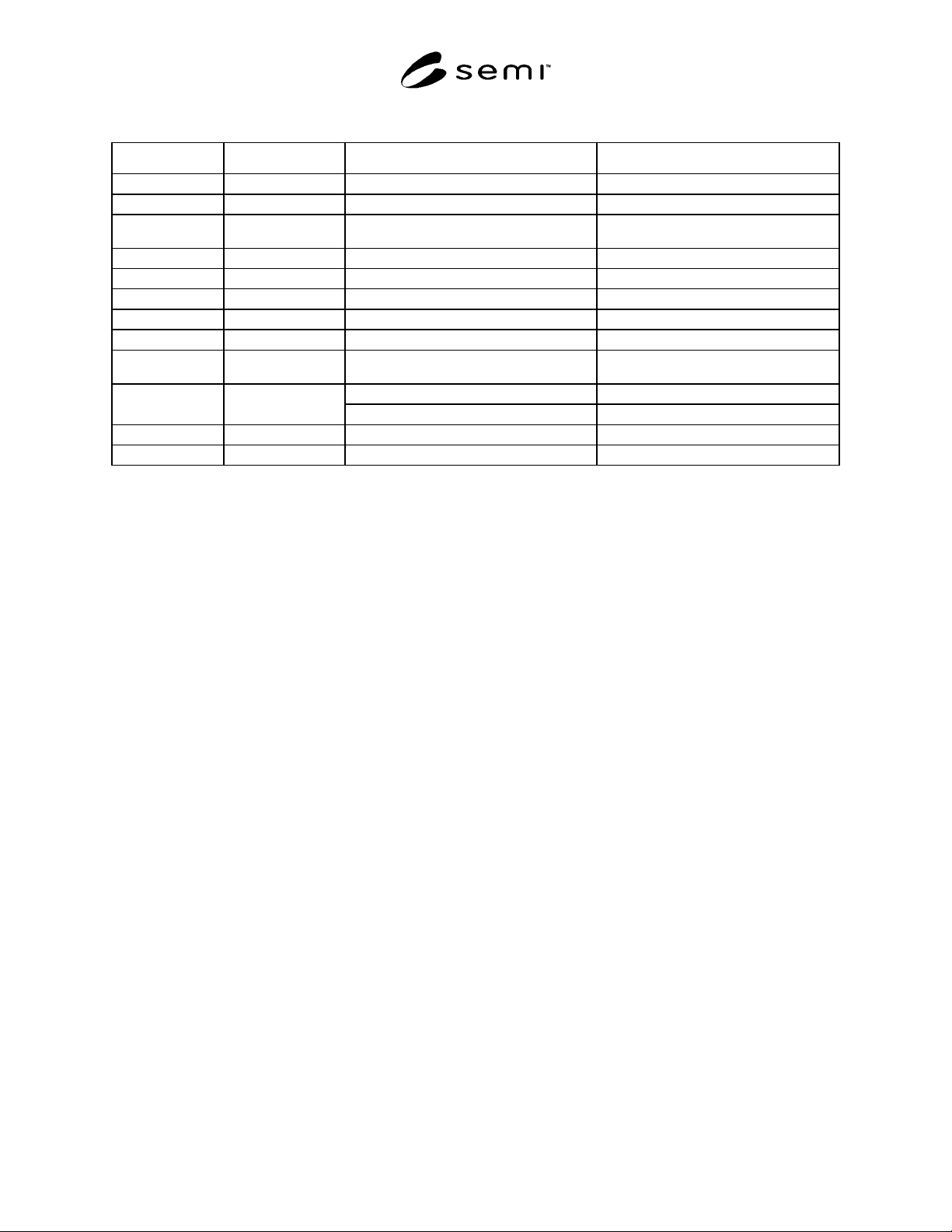
Table 1 Dimensional Requirements for 300 mm Load Port
Dimension Application Value, mm (in.) Notes
C1 minimum 75 (3.0)
C2 minimum 30 (1.2)
D range
250
0
10
+
−
(9.8
0
4.0
+
−
)
D0 minimum 110 (4.33)
H nominal 900 (35.4) 1
H0 minimum 15 (0.59)
H1 maximum 25 (1.0)
H2 maximum 2600 (102.4 )
HC3 range
32
0.2
0
+
−
(1.26
1.0
0
+
−
)
2
482 (19.0) 3
S minimum
555 (21.9) 4
W1 maximum 130 (5.12)
W2 minimum 205 (8.07)
NOTE 1: This value is ergonomically compatible with the proposed 13 frame cassette and may not be ergonomically compatible with the
proposed 25 frame cassette. The proposed 25 frame cassette may require assisted loading. H to be fully adjustable at installation over the range of
890 to 910 mm (35 to 35.8 inches).
NOTE 2: To avoid confusion, HC3 is used instead of H3 because H3 stands for another dimension in SEMI E15.1.
NOTE 3: Frame cassette (see SEMI G77) without manual side handles
NOTE 4: Frame cassette (see SEMI G77) with manual side handles
9 Table 1 Dimensions Definition
9.1 See SEMI E15 for definitions of the following terms used in this specification:
9.1.1 C1
9.1.2 C2
9.1.3 H
9.1.4 H1
9.1.5 S
9.2 D — allowable load depth to frame cassette centroid.
9.3 D0 — minimum rear clearance of equipment boundary below H1 from facial datum plane.
9.4 H0 — minimum height from the bottom of equipment boundary below H1 to horizontal datum plane.
9.5 H2 — maximum overhead track clearance from the floor.
9.6 HC3 — allowable height of conveyor rail from horizontal datum plane.
9.7 W1 — maximum side clearance of equipment boundary below H1 from bilateral datum plane.
9.8 W2 — minimum side clearance of equipment boundary below H1 from bilateral datum plane.