semi合集-English.pdf - 第4164页
SEMI F67-1101 © SEMI 2001 6 Purge Gas DUT Pure Gas (>9N Purity ) AP IM S or Ultra trace An aly tical Instr umen tatio n Impurity Analy zer P1 Legend DUT = Devic e Unde r Test P1 = Test Pr essure R1 = Pu re Gas 0–100 p…

SEMI F67-1101 © SEMI 20015
8.3.7.2 When the impurity level is in the range of the
APIMS or ultratrace analytical instrumentation, Close
V13 and Open V12. Close V9 and V10, Open V11.
8.3.7.3 Monitor impurity level until stable.
8.3.8 Initiate Impurity Challenge:
8.3.8.1 Isolate the DUT and APIMS or ultratrace
analytical instrumentation. Close V7 and V12, open
V13.
8.3.8.2 Open V3 and adjust R2 to the suggested
operating pressure range of 275–415 kPa (40–60 psig).
Open V5 and set MFC2 to the desired flow. (See
Appendix 1 to determine the desired flow for MFC2).
8.3.8.3 Verify test gas impurity. Open V4, V8, and
V10 and then close V5 and V11, supplying test gas to
the impurity analyzer. Adjust R2 as necessary to
maintain appropriate pressure for supplying MFC2.
Monitor test gas impurity until stable and verified to
theoretical impurity value (See Appendix 1).
8.3.8.4 Initiate test. Direct input test gas through the
DUT to the APIMS or ultratrace impurity analyzer,
Open V6 and V7. Open V12 and close V13. Isolate
impurity analyzer, Close V8 and V10. Open V11.
8.3.8.5 Zero test gas flow totalizers (Pure Gas MFC1
and challenge gas through MFC2) beginning Purifier
Capacity Test.
8.3.9 Determination of purifier capacity:
8.3.9.1 The test will require several weeks or months
depending on the purifier’s capacity for retention of and
the concentration of the impurity.
8.3.9.2 The test may be done on newly activated media
or may be done using existing media that has been
regenerated. The test may be destructive to the DUT.
8.3.9.3 Constant monitoring of the purifier effluent
over the duration of the test is preferred. However,
periodic monitoring, e.g. every few hours is sufficient.
8.3.9.4 The test gas can be periodically monitored at
the impurity analyzer by closing V11 and opening V8
and V10. If significant, ensure that flow volume to
impurity analyzer during this time is subtracted from
total volume input through DUT. In addition,
instrument calibration should be monitored as
recommended by the manufacturer.
8.3.9.5 Monitor trends in outlet purity until the
breakthrough point for the impurity is detected. Time,
liters of gas, and outlet purity should be recorded.
8.4 Repeat test for each new impurity to be analyzed
using a new or regenerated DUT.
9 Exposure Precautions
9.1 The APIMS or ultratrace analytical instrument
should not be exposed to high levels of impurities.
After installation of the purifier, it should be purged
well, per the manufacturer’s recommendation. A
typical recommendation might be to purge a minimum
of 150 bed volumes before directing the flow to the
APIMS.
10 Calculation of Purifier Capacity
10.1 Use the following formula to calculate Purifier
Capacity:
10.2 (Test Duration (min)) × (Test Flow Rate slpm) =
Total Liters Test Gas (TLTG)
10.3 Impurity(liters) = (TLTG) × ppm × 10
-6
10.4 Purifier Capacity = (Total Impurity
(liters)/(Purifier Volume(liters))
10.5 Purifier Capacity is reported as total liters of each
given impurity per liter purifier, and is a dimensionless
number.
11 Reporting Results
11.1 The following test conditions should be reported:
11.1.1 Date and time of test,
11.1.2 Operator,
11.1.3 Pure gas flow rate (slpm),
11.1.4 Challenge gas flow rate (sccm),
11.1.5 Test pressure kPa (psig or psia),
11.1.6 DUT operating temperature (° C),
11.1.7 Purifier manufacturer, model, and serial
number, and volume,
11.1.8 Ultratrace analytical instrumentation used,
11.1.9 Test gas impurities and levels, and
11.1.10 Calibration certificates for the mass flow
devices, pressure gauges and ultratrace analytical
instrumentation.
12 Related Documents
SEMI F30 — Start-up and Verification of Purifier
Performance Testing for Trace Gas Impurities and
Particles at an Installation Site
SEMI F43 — Test Method for Determination of
Particle Contribution by Point-Of-Use Purifiers
NOTE 3: Unless otherwise indicated, all documents cited
shall be the latest published versions.
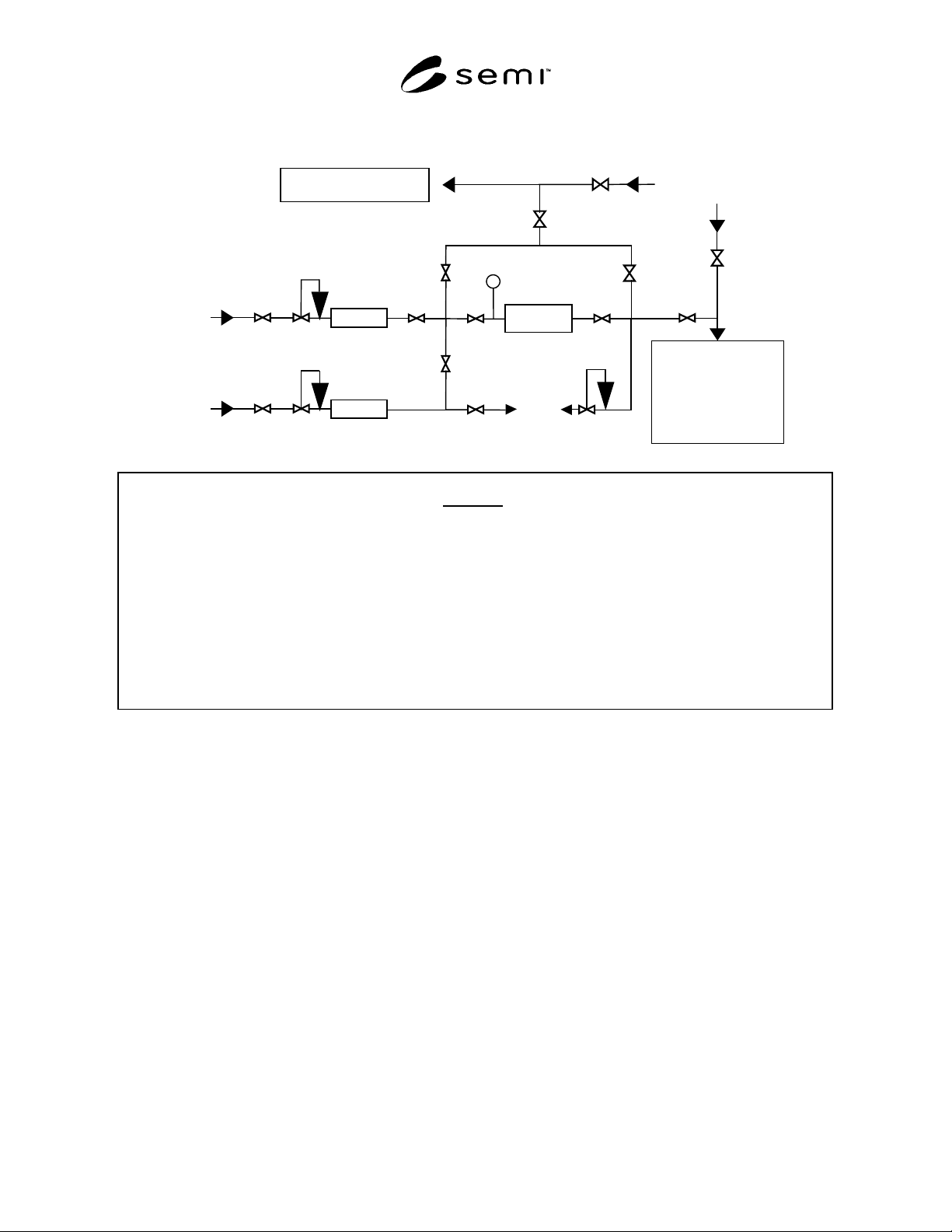
SEMI F67-1101 © SEMI 2001 6
Purge Gas
DUT
Pure Gas
(>9N Purity)
APIMS
or
Ultratrace
Analytical
Instrumentation
Impurity Analyzer
P1
Legend
DUT = Device Under Test
P1 = Test Pressure
R1 = Pure Gas 0–100 psig Regulator
R2 = Challenge Gas 0–100 psig Regulator
R3 = Vent Gas 0–100 psig Back Pressure Regulato
r
V1 = Pure Gas Source Isolation Valve
V2 = Pure Gas System Isolation Valve
V3 = Challenge Gas Source Isolation Valve
V4 = Challenge Gas System Isolation Valve
V5 = Challenge Gas Vent Isolation Valve
Challenge Gas
(~1% Impurity)
V4
V5
V6 V7
V8
V9
Vent
V10
V11
MFC1
R1
V1
V2
V
6 = DUT Inlet Isolation Valve
V7 = DUT Outlet Isolation Valve
V8 = DUT Bypass Inlet Isolation Valve
V9 = DUT Bypass Outlet Isolation Valve
V10 = Impurity Analyzer Sample Isolation Valve
V11 = Impurity Analyzer Purge Gas Isolation Valve
V12 = APIMS/UAI Sample Isolation Valve
V13 = APIMS/UAI Purge Gas Isolation Valve
MFC1 = Pure Gas Mass Flow Controller
MFC2 = Challenge Gas Mass Flow Controller
V13
V12
MFC2
R2
V3
R3
Figure 1
Suggested Point of Use Purifier Capacity Test Setup

SEMI F67-1101 © SEMI 20017
APPENDIX 1
MFC SIZING
NOTE: The material in this appendix is an official part of SEMI F67 and was approved by full letter ballot
procedures on August 27, 2001.
A1-1 To determine purifier efficiency, the
concentration of impurity entering the purifier and the
quantity of impurity downstream of the purifier must be
determined.
A1-2 Determine the manufacturer’s recommended
flow rate for the purifier. As an example, assume a
flow rate of 5 slpm.
A1-3 Determine the flow rate of challenge gas
required. As an example, 5 sccm of a 1% challenge gas
would be blended into 4,995 sccm of pure gas to
generate a 10 ppm test gas.
PPM 10
sccm 4,995sccm 5
sccm 5PPM 10,000
GasTest =
+
×
=
NOTICE: SEMI makes no warranties or
representations as to the suitability of the standard set
forth herein for any particular application. The
determination of the suitability of the standard is solely
the responsibility of the user. Users are cautioned to
refer to manufacturer’s instructions, product labels,
product data sheets, and other relevant literature
respecting any materials mentioned herein. These
standards are subject to change without notice.
The user’s attention is called to the possibility that
compliance with this standard may require use of copy-
righted material or of an invention covered by patent
rights. By publication of this standard, SEMI takes no
position respecting the validity of any patent rights or
copyrights asserted in connection with any item
mentioned in this standard. Users of this standard are
expressly advised that determination of any such patent
rights or copyrights, and the risk of infringement of
such rights, are entirely their own responsibility.
Copyright by SEMI® (Semiconductor Equipment and Materials
International), 3081 Zanker Road, San Jose, CA 95134. Reproduction o
f
the contents in whole or in part is forbidden without express written
consent of SEMI.