semi合集-English.pdf - 第2750页
SEMI E98-1102 © SEMI 2000, 2002 15 AbstractEquipment Element Equipment AbstractEquipmentM odule A bstractE quipment- Subsystem Figure 5 Object Interface Hierarchy Concept 9.6.1.1 Th e physical view shown in Figure 2 is c…
SEMI E98-1102 © SEMI 2000, 2002 14
9.5 OBEM Object Requirements — By definition,
subtypes of objects inherit the properties (attributes,
services, and relationships) of their supertypes. In some
cases, properties of the subtype may be further
specialized.
9.5.1 Object Services Requirements — All objects
formally defined by this standard shall be compliant to
the fundamental requirements of SEMI E39 (OSS). All
OBEM-defined objects that are aggregates, containers,
or managers of other objects shall comply with the
additional OSS requirements for object owners.
According to OSS, an owner is any aggregate,
container, or manager of one or more other objects. An
owner is required to respond to queries about the types
of objects that it owns. Owners have additional
responsibilities, as specified in OSS.
9.5.2 Object Non-volatility
9.5.2.1 All objects defined by OBEM shall be
persistent. The individual object persists across
powerdown and powerup conditions, and all current
values of static attributes (attributes that do not change
dynamically indicating the object' s status) shall be
maintained and restored upon powerup. It may be
important to maintain other critical values as well,
depending upon the object and the implementation.
When the equipment is powdered on or reset
5
, all state
models are restored. Following initialization, the object
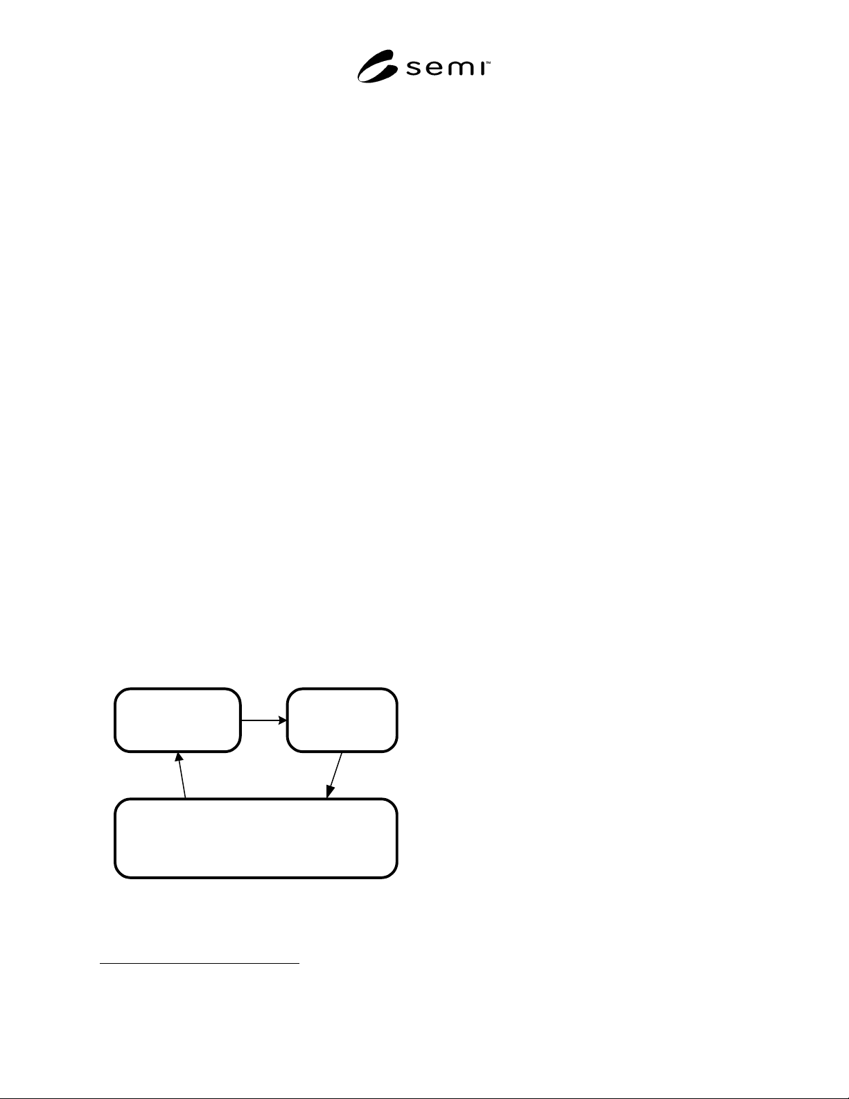
is considered to be operational. Figure 4 shows this
convention for a generic OBEM object. However,
since the state model can not be accessed by the user
until the object is operational, the default entry state for
a specific state model is considered to be within the
Operational state.
(Persistent OBEM Object)
OPERATIONAL
POWER
DOWN
INITIALIZATION
Figure 4
Persistence of OBEM Objects
5 For a more detailed discussion of powerdown, reset, and soft reset,
see SEMI E58.
9.5.2.2 POWERDOWN and INITIALIZATION are
common to all OBEM objects. Therefore, they are not
specific to any object and are not generally shown.
When operational, the OBEM object is capable of
maintaining state information. From the user view, an
instantiation of an OBEM object shall follow the
behavior or state model as shown in Figure 4. The
equipment representation, which consists of an
aggregation of OBEM objects, shall also reflect the
state model shown here.
9.5.2.3 The equipment is responsible for managing the
exchange of any of its component parts, including parts
exchanged during powerdown. This may be
accomplished through use of intelligent components
that are able to identify themselves or through the user
interface.
9.5.3 Shared Resources — When two (or more) objects
cooperate in using the services provided by a third
object, then the third object should not be modeled as a
component of either of the first two objects. If the two
cooperating objects have a common owner, either
logical or physical, then the shared resource object
should belong to the common owner.
9.5.4 Object Factory Communications — OBEM
objects other than the Equipment object are neither
required nor expected to communicate directly with the
factory. Factory communications are handled by the
Equipment instantiation.
9.5.5 Object Event Reporting
9.5.5.1 Event reporting allows a user to receive
notification of events together with related data of
interest. OBEM compliance requires that the equipment
provide a standard mechanism for reporting events of
interest to the user, together with the current values of
user-selectable data.
9.5.5.2 All transitions in state models are of interest to
the user and reportable unless otherwise stated in the
state model definition.
9.6 OBEM Interface Inheritance Hierarchy
9.6.1 An interface inheritance hierarchy begins with a
simple interface at the highest (most abstract) level, and
lower levels within the hierarchy represent added
functionality (specialization). A subtype of an object
inherits the attributes, behavior, relationships, and
services of the supertype and adds to and/or modifies
(overrides) them.
SEMI E98-1102 © SEMI 2000, 2002 15
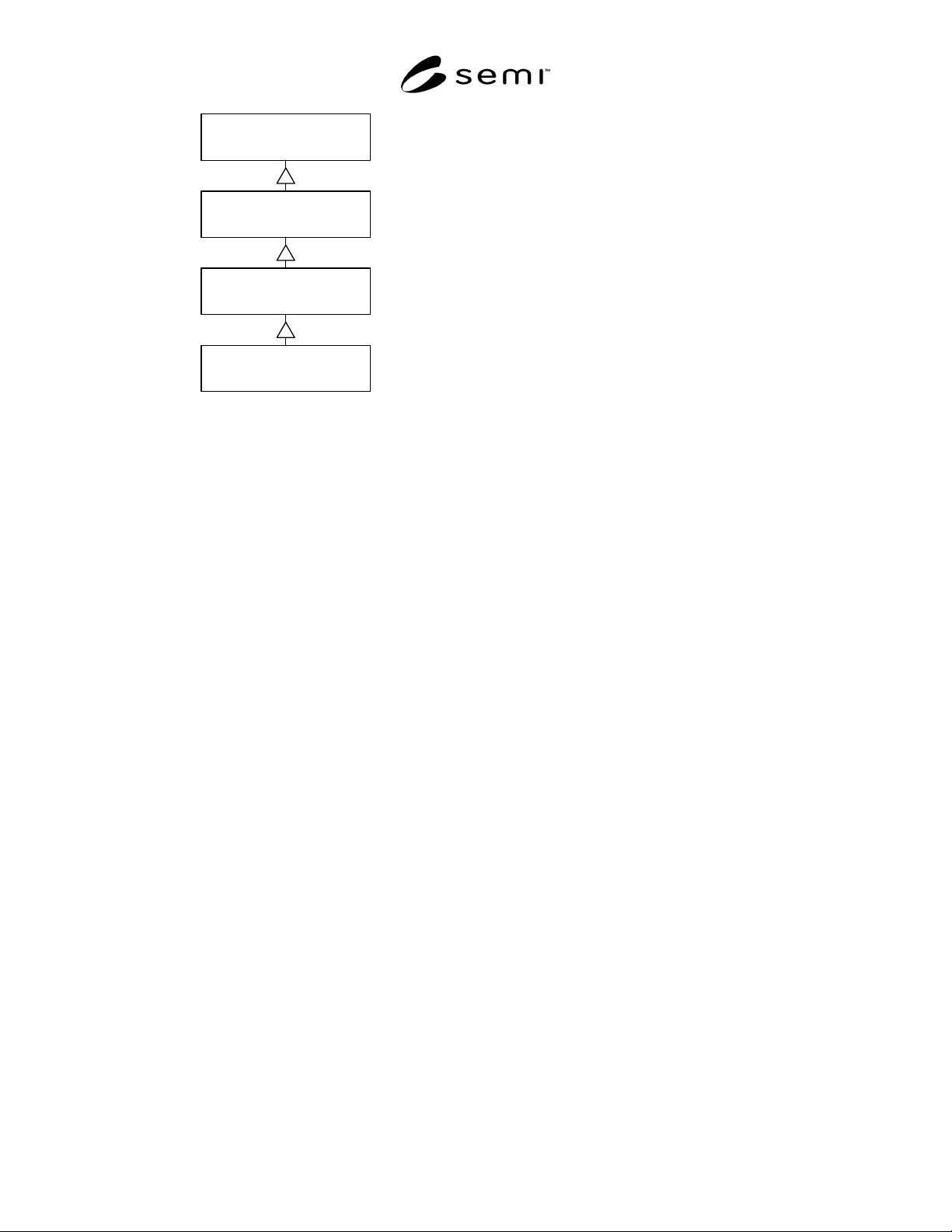
AbstractEquipment
Element
Equipment
AbstractEquipmentModule
AbstractEquipment-
Subsystem
Figure 5
Object Interface Hierarchy Concept
9.6.1.1 The physical view shown in Figure 2 is
concerned with the relationships between different
objects. In that view, the equipment is at the highest
level and owns (is responsible for) the lower level
objects of which it is made up. A process chamber is
considered to be at a higher level than subsystems such
as substrate handlers.
9.6.1.2 From the view of the object interface hierarchy,
this order is reversed, with AbstractEquipmentElement
appearing at the top level as shown in Figure 5. From
the view of an object interface — the interface to an
object — the higher the level, the more simple the
interface. This is because of inheritance, where the
“child” object inherits all of the attributes, behavior,
and services of the “parent” object and at the same time
adds some degree of specialization that will be reflected
in either additional attributes, behavior, or services, or
in restrictions on the more general object.
9.6.1.3 All objects represent the view as seen by the
factory, not the internal view of equipment control.
From this view, the information and services required
for an equipment part such as a pod door opener is
relatively simple. The view of a module such as a
process chamber is more complex but contains all the
elements of the view provided for the simpler part
(functional description, immutable id, etc.). The view
of the equipment is the most complex and includes all
of the attributes and services of the equipment element,
equipment subsystem, equipment module, and the
equipment itself.
9.6.1.4 The object model of equipment presented to the
factory is based on SEMI E39 (OSS). OSS services
allow the factory to “discover” the actual physical
makeup and aggregation hierarchy of the physical view
of equipment illustrated in Figures 2 and 3.
9.6.1.5 Each object is defined in terms of its
requirements, attributes, behavior (state models), and
the services that it is required to support. The
equipment owns all of the objects that it is made of and
is responsible for providing the required behavior.
9.6.1.6 All objects in OBEM inherit the attributes and
services defined for the Top Object as specified in the
Object Service Standard (OSS). This allows the factory
to use object services to request the equipment to
describe its physical view by reporting which objects
that it owns.
9.6.1.7 Note that equipment support for an OBEM
interface to the factory does not imply or require direct
access from the factory to any equipment element.
10 OBEM Object Definitions
10.1 OBEM objects are defined in this section.
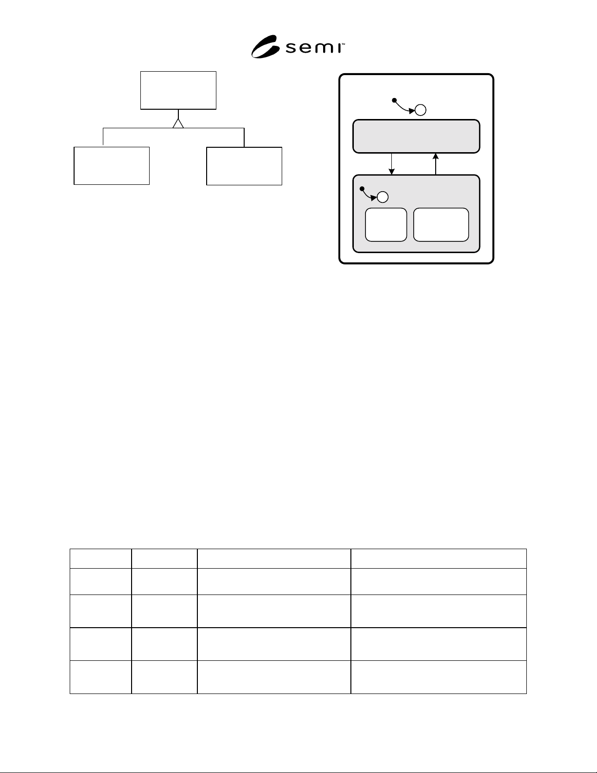
10.2 AbstractEquipmentElement Object — The
supertype object of the interface hierarchy is
AbstractEquipmentElement, which is an abstraction of
any equipment component that can perform work.
AbstractEquipmentElement is an abstract type that is
not implemented directly. There are two subtypes of
AbstractEquipmentElement: AbstractEquipmentSub-
system, and EquipmentIODevice. AbstractEquipment-
Element is an abstract type, so that implementations are
of one of the subtypes.
10.2.1 AbstractEquipmentElement Requirements
10.2.1.1 Object Exception Management
10.2.1.1.1 SEMI E41 defines a model for Exception
Conditions. An Exception Condition may be either an
Alarm Condition or an Error Condition. Error
Conditions may, in some cases, have a set of associated
Recovery Actions that can be performed by the
AbstractEquipmentElement to attempt to recover from
the abnormal situation.
10.2.1.1.2 An OBEM object shall comply with the
fundamental requirements of SEMI E41, Section 10.4.
Exception Condition objects shall be provided in
conformance with SEMI E41 and shall be accessible
through services defined in SEMI E39. The
AbstractEquipmentElement owns all exceptions that it
generates. Therefore, it shall report all of its Exception
Condition objects through OSS services.
10.2.2 AbstractEquipmentElement Subtypes — The
AbstractEquipmentElement has two subtypes, the
EquipmentIODevice and the AbstractEquipment-
Subsystem.
SEMI E98-1102 © SEMI 2000, 2002 16
Abstract
Equipment
Element
Equipment
IODevice
Abstract
Equipment
Subsystem
Figure 6
AbstractEquipmentElement Object Types
10.2.3 AbstractEquipmentElement State Model
10.2.3.1 The AbstractEquipmentElement is either IN
SERVICE (available for work) or OUT OF SERVICE
(unavailable for work). In some cases, the user may be
able to set the AbstractEquipmentElement’s operational
state.
10.2.3.2 The state diagram for the
AbstractEquipmentElement state model is shown in
Figure 7.
10.2.3.3 The AbstractEquipmentElement shall be fault-
free whenever it is in the IN SERVICE state.
10.2.3.4 An AbstractEquipmentElement in the OUT
OF SERVICE state shall not be used by the equipment
or the user for normal manufacturing purposes (while
the Equipment or containing EquipmentModule is in
the ARAMS superstate of MANUFACTURING).
OPERATIONAL
C
1
IN SERVICE
3
USER
SELECT
EQUIPMENT
SELECT
2
C
4
OUT OF
SERVICE
Figure 7
AbstractEquipmentElement State Model
10.2.3.5 The user may or may not be allowed to put a
certain subtype of AbstractEquipmentElement out of
service, depending upon the equipment design. This is
optional for the equipment. In general, the user
requires the ability to put major components into and
out of service but does not require this for lower level
components. In many cases, a component can not
operate without some or all of its component elements.
10.2.3.6 Substates of OUT OF SERVICE are not
required unless the user is able to put the
AbstractEquipmentElement out of service. However, if
a user places an AbstractEquipmentElement out of
service, only a user shall be able to return it back in
service. The substates are then required to retain the
source of the out of service selection through the
substates USER SELECT and EQUIPMENT SELECT.
10.2.3.7 State Model Definitions — Table 2 defines the states of the AbstractEquipmentElement object.
Table 2 AbstractEquipmentElement State Definitions
State Name Superstate Definition Comment
IN SERVICE OPERATIONAL The AbstractEquipmentElement is error-
free and may be used for work.
None
OUT OF
SERVICE
OPERATIONAL The AbstractEquipmentElement has one
or more exceptions and/or has been made
unavailable by the equipment or User.
None
USER SELECT OUT OF
SERVICE
The user requested the Abstract-
Equipment-Element be put out of service.
Stays out of service until the user returns it to
service. This substate may be omitted for low
level elements.
EQUIPMENT
SELECT
OUT OF
SERVICE
The equipment determined that the
AbstractEquipmentElement should be
placed out of service.
Stays out of service until the equipment
determines it is able to operate properly. This
substate may be omitted for low level elements.