semi合集-English.pdf - 第6077页
SEMI G10-96 © SEMI 198 6, 1996 14 The user’s attention is called to the possib ility that compliance w it h this stan dard may require use of copyrig hted m aterial or of an inventi on covered by patent ri ghts. By publi…
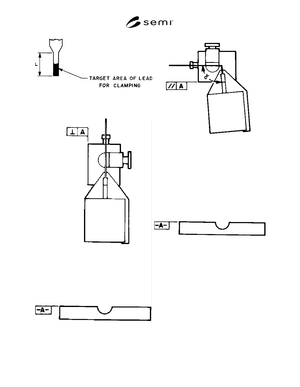
SEMI G10-96 © SEMI 1986, 199613
Figure 19
Frame Location on Lead Fatigue Testing Machine
Front View
Figure 20
Frame Location on Lead Fatigue Testing Machine
Side View
Figure 21
Frame Location on Lead Fatigue Testing Machine
Side View with 90° Rotation
NOTICE: These standards do not purport to address
safety issues, if any, associated with their use. It is the
responsibility of the user of these standards to establish
appropriate safety and health practices and determine
the applicability of regulatory limitations prior to use.
SEMI makes no warranties or representations as to the
suitability of the standards set forth herein for any
particular application. The determination of the
suitability of the standard is solely the responsibility of
the user. Users are cautioned to refer to manufacturer’s
instructions, product labels, product data sheets, and
other relevant literature respecting any materials
mentioned herein. These standards are subject to
change without notice.

SEMI G10-96 © SEMI 1986, 1996 14
The user’s attention is called to the possibility that
compliance with this standard may require use of
copyrighted material or of an invention covered by
patent rights. By publication of this standard, SEMI
takes no position respecting the validity of any patent
rights or copyrights asserted in connection with any
item mentioned in this standard. Users of this standard
are expressly advised that determination of any such
patent rights or copyrights, and the risk of infringement
of such rights, are entirely their own responsibility.
Copyright by SEMI® (Semiconductor Equipment and Materials
International), 3081 Zanker Road, San Jose, CA 95134. Reproduction o
f
the contents in whole or in part is forbidden without express written
consent of SEMI.

SEMI G11-88 © SEMI 1981, 19961
SEMI G11-88
RECOMMENDED PRACTICE FOR RAM FOLLOWER GEL TIME AND
SPIRAL FLOW OF THERMAL SETTING MOLDING COMPOUNDS
1 Scope
This method describes a procedure for measuring the
flow and gel characteristics of semiconductor grade
transfer molding compounds using a ram follower
device.
2 Applicable Documents
1
ASTM D 3123 — Plastics, Molding, and Extrusions
3 Significance
3.1 The flow of a molding compound depends on the
interaction of several variables, and is a measure of the
combined characteristics of speed of gelation and melt
viscosity of the particular compound under the
specified conditions. The test is not a valid method for
comparing the moldability of different compounds
since a spiral flow test cannot duplicate actual molding
conditions in different types of molds.
3.2 The moldability of thermosetti ng molding
compounds has generally been defined by a single
spiral flow number. The ram follower device follows
graphically the molding compound as it melts and the
rate of flow increases, as viscosity builds up due to
resin polymerization, and as the flow of the compound
ceases. Thus, it measures the gelation point of the
compound, or the point where the material ceases to
flow. This information can be an aid in characterizing
the rheological behavior of the molding compound.
4 Apparatus
4.1 Transfer Molding Press — With a platen area
sufficient to maintain a uniform mold temperature and
having (1) a transfer piston pressure potential of 1000
psi on the material; (2) sufficient clamping pressure to
prevent flashing of the molding compound; and (3) a
minimum plunger speed of 25.4 mm (1 inch) per
second without load. The pot diameter shall be 31.75 to
44.45 ± 0.635 mm (1.250 to 1.750 ± 0.025 inch) and the
clearance between pot and ram shall be sufficiently
small that flashing does not occur above the first
sealing groove on the ram.
4.2 Standard Spiral Flow Mold — Per ASTM D 3123.
4.3 Ram Following Apparatus — Consisting of a
displacement transducer attached to the transfer ram of
1 American Society for Testing and Materials, 100 Barr Harbor
Drive, West Conshohoken, PA 19428-2959
the press in such a way as to accurately record its
movement, suitable power supply for the displacement
transducer, and a recorder capable of recording the
signal from the displacement transducer and preferably
having a chart speed of at least 10 mm per second. An
optional velocity transducer can also be used as a
means of directly measuring ram velocity and verifying
the starting and ending of the flow process. In this case,
a 2-channel recorder is needed.
4.4 Thermocouple and Potentiometer — Calibrated in
the 149° to 177°C (300° to 350°F) range. (Calibration
to be checked every six months.)
5 Test Conditions
5.1 Molding Compound — Refrigerated shipment and
storage of some molding compounds is necessary. The
molding compound is to be at room temperature before
the container is opened. Once the compound has
equilibrated to room temperature, the test should be run
within 16 hours. Care must be taken to preserve the
original moisture content. The material should be in
powdered form, unless otherwise specified.
NOTE: Room temperature defined to be 23° ± 5°C.
NOTE: Refer to manufacturers' recommendations regarding
shelf life differences which may exist between molding
compounds.
5.2 The Spiral Flow Mold — Shall be clean and free
from any mold release agents or lubricants. A standard
mold cleaning compound can be used to insure mold
cleanliness.
5.3 Molding Conditions
5.3.1 The temperature of the mold shall be measured
using a thermocouple inserted in the mold. The ram
shall be kept at the mold temperature. Molding
temperature is to be as recommended by the material
specification unless otherwise specified. Temperature
must be maintained within ± 3°C (± 5°F) of the
specified temperature.
NOTE: Flow duration is strongly influenced by temperature.
For critical determinations, the temperature should be
maintained as close to the nominal temperature as practical,
preferably within ± 0.5°C (± 1°F).
5.3.2 The weight of the charge shall be adjusted to
give a molded cull thickness of 3.302 ± 0.254 mm
(0.130 ± 0.010 in.), excluding vertical flash.