semi合集-English.pdf - 第4558页
SEMI D28-1101 © SEMI 2001 2 6.2.9 Z4 — height o f exclusi on z one r equire d for MGV cart alignment equipment. 6.2.10 Z5 — hei ght o f excl usio n for k zone b elow t he horizontal datum plane, which is needed by the tr…

SEMI D28-1101 © SEMI 20011
SEMI D28-1101
SPECIFICATION FOR MECHANICAL INTERFACE BETWEEN FLAT
PANEL DISPLAY MATERIAL HANDLING EQUIPMENT AND TOOL
PORT, USING AUTOMATED GUIDED VEHICLE (AGV), RAIL GUIDED
VEHICLE (RGV), AND MANUAL GUIDED VEHICLE (MGV)
This specification was technically approved by the Global Flat Panel Display Material Handling Committee
and is the direct responsibility of the Japanese Flat Panel Display Material Handling Committee. Current
edition approved by the Japanese Regional Standards Committee on August 3, 2001. Initially available at
www.semi.org September 2001; to be published November 2001.
1 Purpose
1.1 This specification defines a common set of feature
requirements on and about tool ports of process tools
used in manufacturing of flat panel displays. These
standardized feature requirements are intended to
facilitate the interfacing of AGV, RGV, and MGV
equipment to the process tool. Such standards are
intended to promote cost-effective interfacing while
preserving freedom of choice in material handling
equipment, using AGV, RGV, and MGV.
2 Scope
2.1 This specification defines mechanical features on
or about the tool port, and in front of or on the tool face.
Although these features are intended for specific
functions of AGV, RGV, and MGV, the interface
requirements are meant to avoid the promotion of any
particular form of transport.
2.2 This standard does not purport to address safety
issues, if any, associated with its use. It is the
responsibility of the user of these standards to establish
appropriate safety and health practices and determine
the applicability of regulatory limitations prior to use.
3 Limitations
3.1 Current display manufacturing utilizes several
substrate sizes, many of them “non-standard.” This
specification includes dimensions for the substrate sizes
of 550 × 650 mm, 600 × 720 mm, 680 × 880 mm, 730 ×
920 mm, and 800 × 950 mm and anticipates the
establishment of standard dimensions in future substrate
sizes.
4 Referenced Standards
4.1 None.
5 Ordering Information
5.1 Since this document is not a product specification
but an interface specification, ordering information is
not applicable.
6 Terminology
6.1 Definitions
6.1.1 cassette loading position — center point at
under-surface of a cassette after loading by transport
equipment.
6.1.2 facial datum plane — a plane that is parallel to
the tool face and vertical to both vertical and horizontal
datum planes at the cassette loading position.
6.1.3 horizontal datum plane — a plane that is parallel
to the floor surface at the cassette loading position.
6.1.4 vertical datum plane — a plane that is vertical to
both facial and horizontal datum planes at the cassette
loading position.
6.2 Dimensional Functions
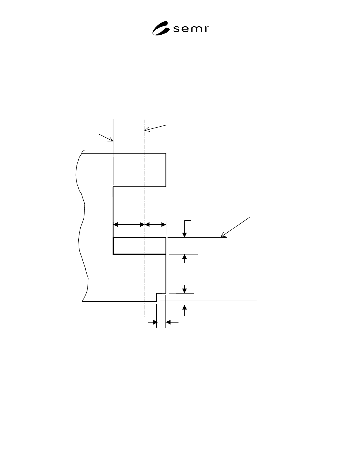
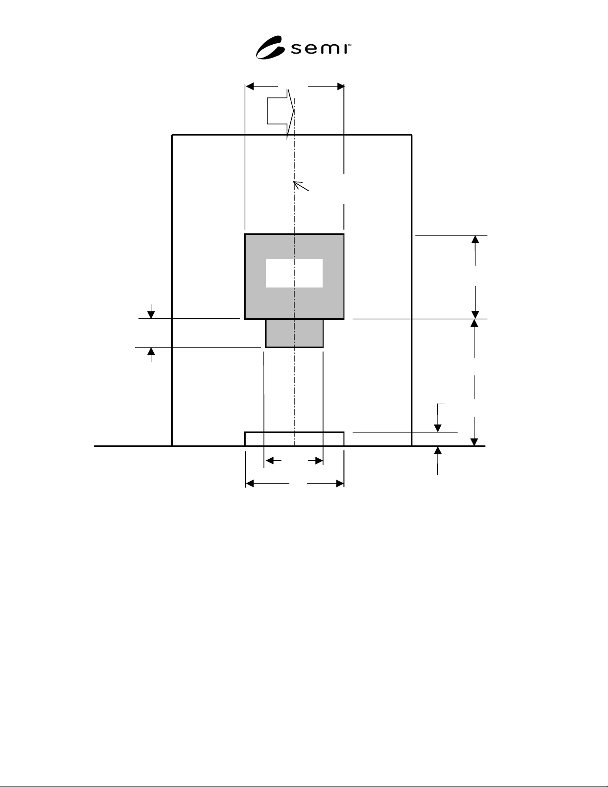
6.2.1 X1 — width of the exclusion zone above the
horizontal datum plane, which is needed by the
transport equipment in loading cassettes.
6.2.2 X2 — width of the exclusion fork zone below the
horizontal datum plane, which is needed by the
transport equipment in loading cassettes.
6.2.3 X3 — width of the exclusion zone required for
MGV cart alignment equipment.
6.2.4 Y1 — dimension between the facial datum plane
and the front of the tool port.
6.2.5 Y2 — dimension between the facial datum plane
and the tool face, which is the exclusion zone needed
by the transport equipment in loading cassettes.
6.2.6 Y3 — depth of exclusion zone required for MGV
cart alignment equipment.
6.2.7 Z1 — height between the horizontal datum plane
and the floor surface.
6.2.8 Z2 — height of exclusion zone above the
horizontal datum plane, which is needed by the
transport equipment in loading cassettes.
SEMI D28-1101 © SEMI 2001 2
6.2.9 Z4 — height of exclusion zone required for MGV
cart alignment equipment.
6.2.10 Z5 — height of exclusion fork zone below the
horizontal datum plane, which is needed by the
transport equipment in loading cassettes.
7 Requirements
7.1 Dimensions and tolerances of the required
characteristics are shown in Table 1 as well as Figures
1A and 1B.
7.2 The cassette is stored horizontally with the shorter
side parallel to the tool face and horizontal datum
plane.
Z5
Y3
Z4
Tool
Tool face
(Equipment
Boundary)
Horizontal Datum Plane
Y2 Y1
Facial datum plane
(cassette centroid)
Figure 1A
(Arrow ’A’ View)
Side View of Tool port
SEMI D28-1101 © SEMI 20013
X1
Z1
Z4
X2
Z5
Exclusion
Zone
Vertical
Datum Plane
Z2
A
X
3
Figure 1B
Front View of Tool port