semi合集-English.pdf - 第1508页
SEMI E32-0997 © SEMI 1994 , 1997 3 SEMI E32-0997 MA TE RIA L MOV EME NT MA NA GEME NT (M MM) 1 Introduction Automated material m oveme nt represents a sig nificant milestone in the evolution of auto m ation i n semico nd…
SEMI E32-0997 © SEMI 1994, 1997 2
Table 4.2 Atomic Transfer State Transition Table
Table 4.3 Extended Transfer Job State Transition
Table
Table 4.4 Extended Atomic Transfer State
Transition Table
Table 4.5 Equipment Object Definition Table
Table 4.6 TransferJob Object Definition Table
Table 4.7 AtomicTransfer Object Definition Table
Table A1-1 Extended Atomic Transfer State
Transition Table
List of Figures
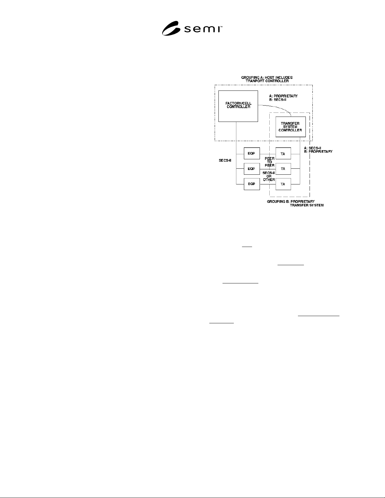
Figure 1.1 Illustration of Material Movement
Scope
Figure 3.1 Port vs. Location
Figure 4.1 Transfer Job Sequencing
Figure 4.2 Macro Level Message Flow
Figure 4.3 Macro Level Messaging With Events
Figure 4.4 Transfer Job State Diagram for a Single
Port
Figure 4.5 Transfer Job State Model for Multiple
Ports
Figure 4.6 Atomic Transfer State Diagram
Figure 4.7 Extended Transfer Job State Model
Figure 4.8 Extended Atomic Transfer State
Diagram
Figure 5.1 Micro Level Message Flow
Figure 5.2 Micro Level Message Flow via Host
Figure A1-1 Example Port State Diagram
SEMI E32-0997 © SEMI 1994, 19973
SEMI E32-0997
MATERIAL MOVEMENT MANAGEMENT (MMM)
1 Introduction
Automated material movement represents a significant
milestone in the evolution of automation in
semiconductor manufacturing. The standardization of
the transfer process is critical to the economic viability
of material movement automation. This standard
addresses the communications needs of the
semiconductor manufacturing facility with respect to
material movement.
1.1 Purpose — This standard addresses automated
material movement on the semiconductor factory
floor—the task of transporting objects (material, et al)
from one processing or storage location to another. It
defines the concepts of material movement, the
behavior of the equipment (including transfer devices)
in relation to material movement, and the messaging
services which are needed to accomplish the task.
1.2 Scope — The scope of this standard is defined
from two viewpoints. The first is the breadth of the
functionality covered. The second is the depth to which
it is covered.
The breadth of functionality covered by this standard is
limited to the activity required to transfer an object
from a location on entity “A” to a location on entity
“B” under the supervision of a factory host. This
transfer may occur directly between two factory process
equipment, or may involve the assistance of a “transfer
agent”, a device dedicated to material transfer. Thus,
the material movement domain includes a maximum of
four types of entities (see Figure 1.1):
Figure 1.1
Illustration of Material Movement Scope
1. The factory host, which might, for example, be a
factory controller or cell controller.
2. The set of process-related equipment, to which the
host communicates.
3. The transfer agent, which performs the physical
transport of the material in the factory. The transfer
agent might communicate directly with the host or
be controlled by an intermediate system.
4. This intermediate system, the transfer system
controller, is the fourth type of entity.
This document assumes that the transfer system
controller is either a part of the host or a part of a
potentially complex transfer agent (as shown by the
dotted boxes in Figure 1.1). Thus, the term “transfer
system controller” seldom appears. The case where a
“transfer agent” is actually a transfer system controller
plus multiple transport devices is discussed further in
Section 4.1.6.
There are some forms of material movement that do not
fall within the domain of this standard and thus are not
applicable to the methods described below. One
example might be a non-deterministic system, such as a
conveyer where generic parts are placed onto the
system and circle until randomly selected by a
workstation needing that type of part.

SEMI E32-0997 © SEMI 1994, 1997 4
The subject of alarm reporting is not covered in this
document. While material movement-related alarm
situations will exist, the definition of the mechanism for
reporting such alarms is left to other standards
documents.
This standard presents a solution from the concepts and
behavior down to the messaging services. It does not
define the messaging protocol.
A messaging service includes the identification that a
message shall be exchanged and definition of the data
contained within that message. It does not include
information on the structure of the message, how the
data is represented within the message, or how the
message is exchanged. This additional information is
contained with the message protocol.
The defined services may be applied to multiple
protocols. Information on the mapping of material
movement services to specific protocols (e.g., SECS-II)
are added as adjunct standards.
1.3 References — The following SEMI standards are
related to the Material Movement standard:
SEMI E5 — SEMI Equipment Communications
Standard 2 Message Content (SECS-II)
SEMI E23 — Specification for Cassette Transfer
Parallel I/O Interface
SEMI E30 — Generic Model for Communications and
Control of SEMI Equipment (GEM)
SEMI E39 — Object Services Standard: Concepts,
Behavior, and Services
Other References:
ISO/TR 8509:1987, Information Processing Systems,
Open Systems Interconnection — Service Conventions
Harel, D., “Statecharts: A Visual Formalism for
Complex Systems,” Science of Computer Programming
8 (1987) 231–274
1
1.4 Conventions
1.4.1 State Models
Definition of behavior of systems or subsystems is
based upon state models using the Harel notation. A
discussion of this notation is available in the article by
David Harel referenced above.
The Harel notation does not include the concept of
“creation” and “deletion” of state models to represent
transient entities. The “transfer job” described in this
document is such an entity, where each new transfer job
1 A brief tutorial on the Harel Statechart Notation is provided as
Application Note A.5 of the SEMI E30 (GEM) standard.
created uses a copy of the same state model. In this
document, the use of an oval is used to denote the
creation of an entity and also the deletion of that entity.
Transition tables are provided in conjunction with the
state diagrams to describe explicitly the nature of each
state transition. A transition contains columns for
Transition #, Current State, Trigger, New State,
Action(s), and Comment. The “trigger” (column 3) for
the transition occurs while in the “current” state. The
“actions” (column 5) include a combination of (1)
actions taken upon exit of the current state, (2) actions
taken upon entry of the new state, and (3) actions taken
which are most closely associated with the transition.
No differentiation is made.
1.4.2 Object Services — SEMI E39 Object Services
Standard (OSS) requires that standardized objects be
subtypes of the Top Object, that their attributes be
defined in a table format and include specification of
the value for object type, and that the objects support
the GetAttr and SetAttr services. See SEMI E39 for
details.