semi合集-English.pdf - 第3454页
SEMI E134-0305 © SEMI 2004, 2005 7 Tim e Sam pli ng W i ndow ( End) Sam p li ng W in dow ( St a r t ) Sampling Window Figure 3 Un-buffered Data Transmission S am pl i ng W i ndo w Sw itch N Tim e Sw it ch 1 B u f f e r i…
SEMI E134-0305 © SEMI 2004, 2005 6
6.2.6.4 Responder/Receiver — For RR semantics, identifies the entity that responds to the request, for FF
semantics, identifies the entity that receives the message. Can be either ‘consumer’ or ‘equipment’.
6.2.7 Operation Argument Definition Table — The table below provides an example of the tables used to list and
describe arguments for interface operations defined in this specification.
Table 4 Operation Argument Definitions
Argument Description Kind Form
See list below See list below
6.2.7.1 Argument — Specifies the name of the argument.
6.2.7.2 Kind — Specifies whether the argument is an ‘in’, ‘out’, or ‘error’ argument for the operation. ‘error’
arguments always function as ‘out’ arguments, but indicate that the operation did not complete successfully. All
possible errors that could be returned by an operation are listed in these tables. Unless otherwise indicated, only one
of the listed errors can be returned by an operation in a single invocation.
6.2.7.3 Form — Defines the data type of the argument. The terms used to describe data types in this column are
defined in the SEMI Compilation of Terms, or are included as part of the specification. Refer to the compilation of
terms for the definition of SEMI type name meanings.
7 Background
7.1 Equipment Data Collection
7.1.1 Manufacturing equipment can be comprised of hundreds or thousands of components that interoperate in
order for the equipment to perform its intended function. The volume of information that such equipment can
produce, and the variation among equipment users in the data used for process control and other applications, makes
it impractical to send all equipment data off-tool all the time, or to agree on a fixed set of data to make available for
each equipment type. It is therefore important for the equipment to support the ability for consumers to dynamically
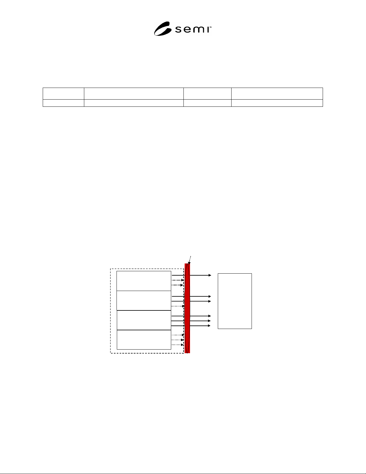
define the data that is of interest to them (see Figure 2).
Wafer Handling
Subsystem
Pump Subsystem
Mass Flow
Controller
…others…
Consumer
Equipment
Requested Data
Figure 2
Consumer Specifies What Data Should Be Sent Off-Tool
7.1.2 In addition to declaring interest in specific data that a consumer is interested in, different consumers have
different requirements for the acceptable latency with which data should be reported off-tool. For example, a
consumer that is monitoring a trace of several process variables in order to detect an excursion needs to have this
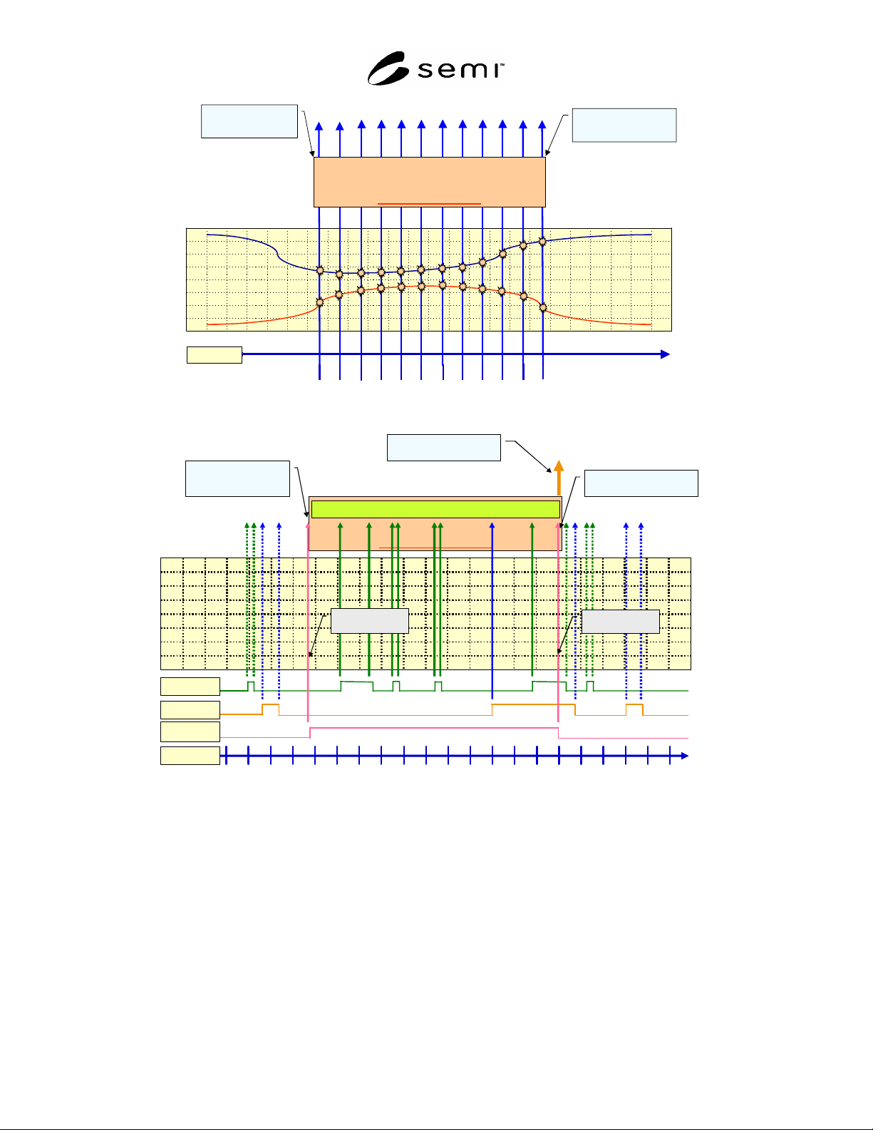
data available off-tool almost as quickly as the equipment can produce it (see Figure 3). A consumer that is
monitoring low-level sensor/actuator activity for later diagnosis prefers not to have all of this data transmitted as it is
produced, but buffered on the tool and transmitted at periodic intervals (see Figure 4).
SEMI E134-0305 © SEMI 2004, 2005 7
Time
Sampling Window
( End)
Sampling Window
( Start)
Sampling Window
Figure 3
Un-buffered Data Transmission
Sampling Window
Switch N
Time
Switch 1
Buffering
buffering
Buffer I nterval
Begin
Buffer I nterval
End
Sampling W indow
( End)
Sampl ing W indow
( St ar t )
Send all buffered data
in one message
Figure 4
Buffered Data Transmission
7.1.3 Because a single tool is likely to have more than one consumer simultaneously interested in these different
styles of data collection, a method for managing groups of related data as a unit can make it easier for consumers to
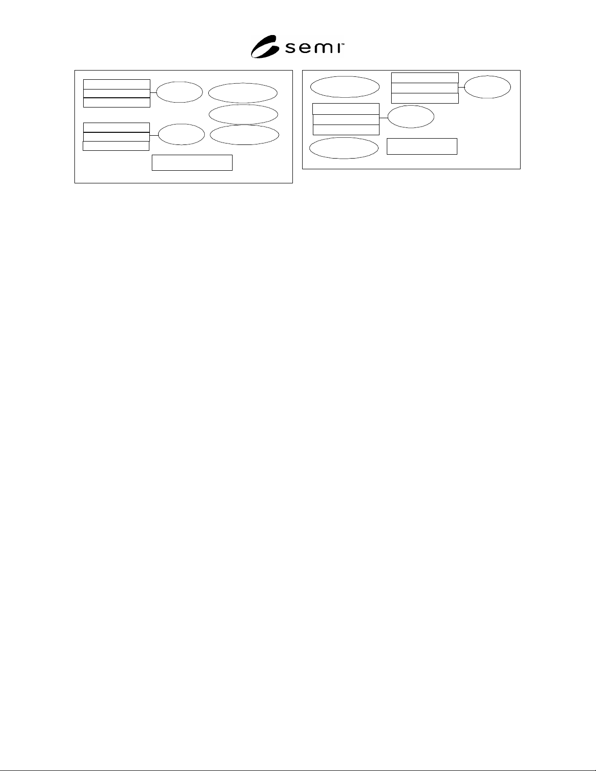
define, enable, and disable the transmission of data. An example of this organization is shown in Figure 5.
SEMI E134-0305 © SEMI 2004, 2005 8
Parameter A
Event A
Event B
Exception A
Exception B
Exception C
Parameter B
Parameter C
Parameter D
Parameter F
Parameter G
Utilization Data Collection Plan
DCP Buffering Interval
= 5 minutes
Trace A
Exception J
Exception B
Parameter L
Parameter X
Parameter T
Process Data Collection Plan
DCP Buffering
Interval = disabled
Parameter A
Event Z
Parameter B
Parameter C
Figure 5
Data Collection Schemes with Different Objectives
7.1.4 It is possible for consumers to submit data collection requests which, when executing together, significantly
tax the equipment’s computing resources. When the equipment detects that this is occurring, it should be able to
provide a warning to consumers that a performance threshold is being reached. Consumers can respond to these
warnings by adjusting or disabling the active data collection requests. In the worst case, if the equipment determines
that continuing to operate under degraded performance conditions may seriously jeopardize its ability to perform its
intended function, the equipment can terminate all data collection activity.
7.1.5 This specification describes the concepts and behaviors necessary to facilitate these capabilities on equipment.
8 Overview
8.1 Data Collection Concepts
8.1.1 This specification allows consumers to describe a set of data in which they are interested, and to ask the
equipment to send only that data off-tool, according to a buffering policy specified by the consumer. The types of
data that are supported by this specification are described in the following sections.
8.2 Trace Data
8.2.1 Trace data allows data acquisition consumers to request the collection of data values that are continuously
changing, or that change frequently such as pressure, temperature, RF power, magnetic field strength, or individual
actuator state changes, etc. This document defines a mechanism for specifying when trace data collection begins
and ends, what the collection frequency is, and what variables are to be collected in the trace (see Section 11.1.5).
8.2.2 This specification defines a mechanism for specifying when to start tracing (see Section 11.1.5.6):
On the occurrence of a specific event or exception from a set of possible events and exceptions
As soon as enabled
8.2.3 This specification defines a mechanism for specifying when to stop tracing (see Section 11.1.5.7):
On the occurrence of a specific event or exception from a set of possible events and exceptions
After a specified number of collection results have been accumulated
As soon as disabled
8.2.4 This specification defines a mechanism for identifying parameters to be included in trace data collection (see
Section 11.1.9). Consumers can use any naming convention supported by the equipment, provided that such
conventions can support the concept of a parameter source and a parameter name represented as text fields.
8.2.5 This specification defines a mechanism to support on-tool buffering, allowing trace reports containing many
collection results to be sent off-tool at a regular interval (see Sections 11.1.2.3 and 11.1.5.3).
8.3 Events
8.3.1 Events allow data acquisition consumers to determine when a subsystem, process job, sensor/actuator, or
other modeled system undergoes a state transition. Events may have data variables associated with the occurrence