semi合集-English.pdf - 第3821页
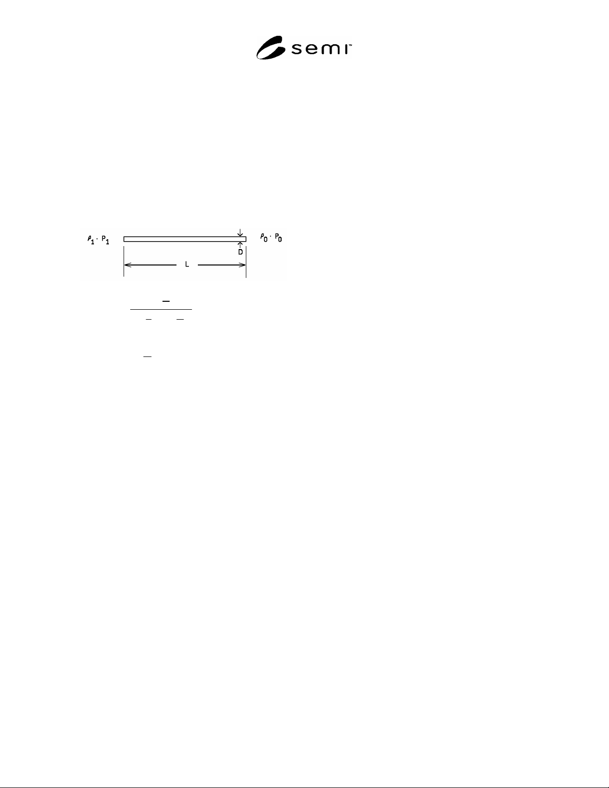
APPENDIX 2 EQUATION FOR FLOW IN A STRAIGHT TUBE NOTICE : The material in this appendix is an official part of SEMI F15 and was approved by full letter ballot procedures. A2-1 A2-1.1 Flow in a straight tube may be calcula…

APPENDIX 1
EQUILIBRIUM TIME FOR TRACER INJECTION
NOTICE: The material in this appendix is an official part of SEMI F15 and was approved by full letter ballot procedures.
A1-1
A1-1.1 If a tracer gas is injected at a constant rate into
an enclosure that possesses a constant ventilation rate,
the concentration as a function of time is given as
C(t) = (F/q) [1 - exp{-(q/V)t}] (A1 -1)
where C t Concentration within the enclosure
F Injection rate of tracer gas
q Ventilation rate of enclosure
V Volume of enclosure
t Elapsed time since initiating injection
A1-1.2 Note that the term (q/V) contained in the
exponential is the air change rate. In order for the
concentration C(t) to be constant, the exponential term
must be approximately zero. This is generally taken as
the time when the exponential term is equal to e
-3
. The
time at which this occurs can be found by setting (q/V)t
= 3 and solving for t. Thus,
(q/V)t = 3 A1- 2
from which it follows that the equilibrium time is given
as,
t 3/(q/V) (A1- 3)
t = 3(V/q) (A1-4)
SEMI F15-93 © SEMI 1993, 2004 5
APPENDIX 2
EQUATION FOR FLOW IN A STRAIGHT TUBE
NOTICE: The material in this appendix is an official part of SEMI F15 and was approved by full letter ballot procedures.
A2-1
A2-1.1 Flow in a straight tube may be calculated if the
tube characteristics, as well as the upstream and
downstream pressures, are known. In the following, the
upstream (drive side) conditions have a subscript of 1,
while the downstream (ambient) conditions have a
subscript of 0.
M
1
2
1
P
0
P
1
2
4 f
L
D
ln
P
1
P
0
2
(A2 -1)
W=A(
1
P
1
M
1
2
)
0.5
(A2 - 2)
1
0
P
1
P
0
(A2 - 3)
where
0
0.00129 g
/
cm
3
1.4
P
Pressure dynes/cm
2
4
f
0.02
for
smooth
pipe
L
Length cm
D
Diameter cm
W
Mass Flowrate g/sec
A
Area of Flow Line cm
2
NOTE 1: Atmospheric pressure, 10
6
dynes/cm
2
, is
approximately 14.7 psia.
SEMI F15-93 © SEMI 1993, 2004 6

APPENDIX 3
GENERAL EQUATION RELATING PROCESS GAS FLOW RATE TO
TRACER INJECTION RATE
NOTICE: The material in this appendix is an official part of SEMI F15-93 and was approved by full letter ballot procedures.
A3-1
A3-1.1 In this appendix, a general equation relating
process gas flow rate, tracer injection flow rate, and
measured SF
6
concentration outside an enclosure to the
ERC is provided. In the following, Q and L are given
in volume units per unit time. Concentrations C are
given in units of either vol./vol. or %. Whatever units
are chosen should be used consistently in Equation A3-
7.
A3-1.2
Let the tracer injection rate into a volume be Q
and the ventilation rate in this volume is L. At
equilibrium, the concentration of tracer within this
volume is Q/L = C
source
. If, in the laboratory, one
measures a concentration of tracer gas C
lab
, then the
Dilution Ratio, D, can be calculated as equal to
C
lab
/C
source
]
tracer
= D
tracer
(A3-1)
For any conserved chemical species, D is constant.
Thus, for a process gas released within the volume, one
can form an analogous ratio
C
lab
/C
source
]
process
= D
process
(A3-2)
For all conserved chemical species, D is constant, hence
D
tracer
= D
process
(A3-3)
From this, one can form
C
lab
/C
source
]
tracer
= C
lab
/C
source
]
process
(A3-4)
so that
C
lab
/C
source
]
tracer
C
source
]
process
= C
lab
]
process
(A3-5)
Here C
lab
]
process
is the previously identified ERC.
For releases in the same test volume, this equation can
be written
{C
lab
]
tracer
(Q/L)]
process
}/ (Q/L)]
tracer
= ERC (A3-6)
Since the ventilation rate is the same
C
lab
]
tracer
Q
process
/ Q
tracer
= ERC (A3-7)
A3-1.2.1 This equation allows the calculation of ERC
when simulating a leak within an enclosure using a
different diameter tubing or different flowrate. In the
case where the flowrates (or tubing size and injection
pressure) are the same for the tracer and the process
gas, Equation A3-7 simplifies to that in Section 5.1.
NOTICE: SEMI makes no warranties or
representations as to the suitability of the standards set
forth herein for any particular application. The
determination of the suitability of the standard is solely
the responsibility of the user. Users are cautioned to
refer to manufacturer's instructions, product labels,
product data sheets, and other relevant literature,
respecting any materials or equipment mentioned
herein. These standards are subject to change without
notice.
By publication of this standard, Semiconductor
Equipment and Materials International (SEMI) takes no
position respecting the validity of any patent rights or
copyrights asserted in connection with any items
mentioned in this standard. Users of this standard are
expressly advised that determination of any such patent
rights or copyrights, and the risk of infringement of
such rights are entirely their own responsibility.
Copyright by SEMI® (Semiconductor Equipment and Materials
International), 3081 Zanker Road, San Jose, CA 95134. Reproduction of
the contents in whole or in part is forbidden without express written
consent of SEMI.
SEMI F15-93 © SEMI 1993, 2004 7