semi合集-English.pdf - 第5907页
SEMI P39-0304 E2 © SEMI 2004 10 edge, and the startin g point. When describing a po lygon, vertex-count must be an even number greater than or equal to 2. 7.7.3 A point-list of type 1 consists of a list of 1-deltas , rep…
SEMI P39-0304
E2
© SEMI 2004 9
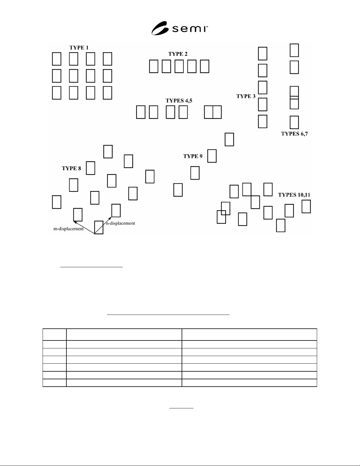
Figure 5
Repetition Types
7.6.14 EXCEPTION HANDLING
— A repetition type outside the range of 0 to 11 should be treated as a fatal error.
A repetition type of 0 may not be the first repetition type used within a cell.
7.7 Point Lists
7.7.1 A point-list represents a list of geometric coordinates for polygons or paths, and consists of an unsigned-
integer denoting its type, followed by a list of deltas, in one of several formats. The initial vertex at (x,y) is supplied
by the POLYGON or PATH record and is not part of the point-list; vertex-count (an unsigned-integer) is the
number of points or deltas, excluding the initial vertex and any implicit vertices
.
Table 7 Point List Types
Type Format Description
0
vertex-count [ 1-delta [ ... 1-delta ] ] Implicit manhattan delta point-list (horizontal-first)
1
vertex-count [ 1-delta [ ... 1-delta ] ] Implicit manhattan delta point-list (vertical-first)
2
vertex-count [ 2-delta [ ... 2-delta ] ] Explicit manhattan delta point-list
3
vertex-count [ 3-delta [ ... 3-delta ] ] Explicit octangular delta point-list
4
vertex-count [ g-delta [ ... g-delta ] ] Explicit all-angle delta point-list
5
vertex-count [ g-delta [ ... g-delta ] ] Explicit all-angle double-delta point-list
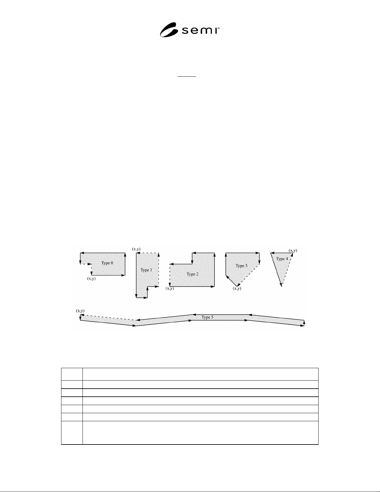
7.7.2 A point-list of type 0 consists of a list of 1-deltas, representing alternating horizontal and vertical relative
displacements, with the first displacement implicitly horizontal
. When describing a polygon point-list in this form,
the final two displacements are omitted, since they can be unambiguously implied from the current point, the last
SEMI P39-0304
E2
© SEMI 2004 10
edge, and the starting point. When describing a polygon, vertex-count must be an even number greater than or equal
to 2.
7.7.3 A point-list of type 1 consists of a list of 1-deltas, representing alternating vertical and horizontal relative
displacements, with the first displacement implicitly vertical
. When describing a polygon point-list in this form, the
final two displacements are omitted, since they can be unambiguously implied from the current point, the last edge,
and the starting point. When describing a polygon, vertex-count must be an even number greater than or equal to 2.
7.7.4 A point-list of type 2 consists of a list of 2-deltas, representing a series of manhattan relative displacements.
When describing a polygon point-list in this form, the final displacement is omitted, since the polygon is assumed to
be implicitly closed, but this final implicit displacement must be a manhattan displacement, with either x = 0 or
y = 0.
7.7.5 A point-list of type 3 consists of a list of 3-deltas, representing a series of octangular relative displacements.
When describing a polygon point-list in this form, the final displacement is omitted, since the polygon is assumed to
be implicitly closed, but this final implicit displacement must be an octangular displacement at an angle that is an
integral multiple of 45°.
7.7.6 A point-list of type 4 consists of a list of g-deltas, representing a series of any-angle relative displacements.
When describing a polygon point-list in this form, the final displacement is omitted, since the polygon is assumed to
be implicitly closed.
7.7.7 A point-list of type 5 consists of a list of g-deltas, representing a series of adjustments to a relative
displacement vector, with the initial vector set to (x = 0, y = 0). To calculate the coordinates of each successive
point, the x and y components of each successive g-delta are added to the relative displacement vector, which in turn
describes the relative displacement from the current point to the next point. When describing a polygon point-list in
this form, the final displacement is omitted, since the polygon is assumed to be implicitly closed. This form of point-
list is intended to allow more compact representation of polygons and paths which are approximations of large-field
curvilinear figures on a fine grid, where the curvature is not extreme.
Figure 6
Point List Describing Polygons
Table 8 Polygon Point List for Figure 6
Type Bit Pattern
0 00000000 00000100 00001100 00001000 00010001 00000101
1 00000001 00000100 00010001 00000100 00000100 00000100
2 00000010 00000101 00100000 00011001 00010010 00001011 00010010
3 00000011 00000100 00010101 00100001 00110000 00010011
4 00000100 00000010 01000100 00001001 00001101
5 00000101 00001001 00000001 00000011 00101001 00000000 00000001 00000100
00000001 00000011 00000001 00000011 00101011 00000100 00101011 00000000
00000001 00000011 00000001 00000011
SEMI P39-0304
E2
© SEMI 2004 11
7.7.8 EXCEPTION HANDLING — A point-list type outside the range of 0 to 5 should be treated as a fatal error.
For point-list types 0-1, successive coincident points and/or adjacent colinear edges are not permitted. A non-
manhattan implicit closing vector for a polygon using point-list type 2, or a non-octangular implicit closing vector
for a polygon using point-list type 3 should be treated as a fatal error. For polygons using point-list types 0-1, a
vertex count which is odd or less than 2 should be treated as a fatal error.
7.8 Property Values
7.8.1 A property-value stores one element of a property value list. It consists of an unsigned-integer which encodes
its type, followed by either the value itself or a reference number. Types 0-7 are reals which conform to the scheme
described in Table 3 on page 5.
Table 9 Property Value Types
Type Format
0-7 real (see Table 3)
8
unsigned-integer
9
signed-integer
10
a-string
11
b-string
12
n-string
13 propstring-reference-number (implied a-string)
14 propstring-reference-number (implied b-string)
15 propstring-reference-number (implied n-string)
7.8.2 EXCEPTION HANDLING
— A property-value type outside the range of 0 to 15 should be treated as a fatal
error. Use of a propstring-reference-number for which there is no corresponding PROPSTRING record within
the same OASIS file should be treated as a fatal error.
8 CELL Referencing
8.1 As in GDSII Stream, cells in OASIS are identified by name
. The CELL record not only introduces a cell
definition but also defines its name. PLACEMENT records refer by name to the cell being placed. As in GDSII
Stream, there are no “anonymous” cells in OASIS.
9 Layers, Datatypes, and Texttypes
9.1 As in GDSII Stream, every <geometry> has associated with it a layer number and a datatype number and every
text element has associated with it a textlayer number and a texttype number.
10 Modal Variables
10.1 For compaction purposes, selected data elements in many OASIS records may be implicitly specified through
the use of modal variables or stored state. At the beginning of the file, and whenever a CELL or <name> record is
encountered, all modal variables with the exception of placement-x, placement-y, geometry-x, geometry-y, text-x,
and text-y, are set to a state of undefined; the exceptions just mentioned are set to 0. As various elements appear in
the cell’s description, modal variables related to those elements are set from the elements’ definitions. These modal
variables can then be used implicitly by successive elements. A modal variable may hold a single value such as
geometry-w, or a multi-variable structure such as a repetition.