semi合集-English.pdf - 第3980页
SEMI F42-0600 © SEMI 199 9, 2000 12 The user’s attention is called to the possib ility that compliance with this te st method may require use of copyrig hted m aterial or of an inventi on covered by patent rights. By pub…
SEMI F42-0600 © SEMI 1999, 200011
RELATED INFORMATION 1
SAG GENERATORS
NOTE: This related information is not an official part of SEMI F42 and has been derived from the work of the originating task
force. This related information was approved for publication by full letter ballot procedures on December 18, 1998.
Determination of the suitability of the material is solely the responsibility of the user.
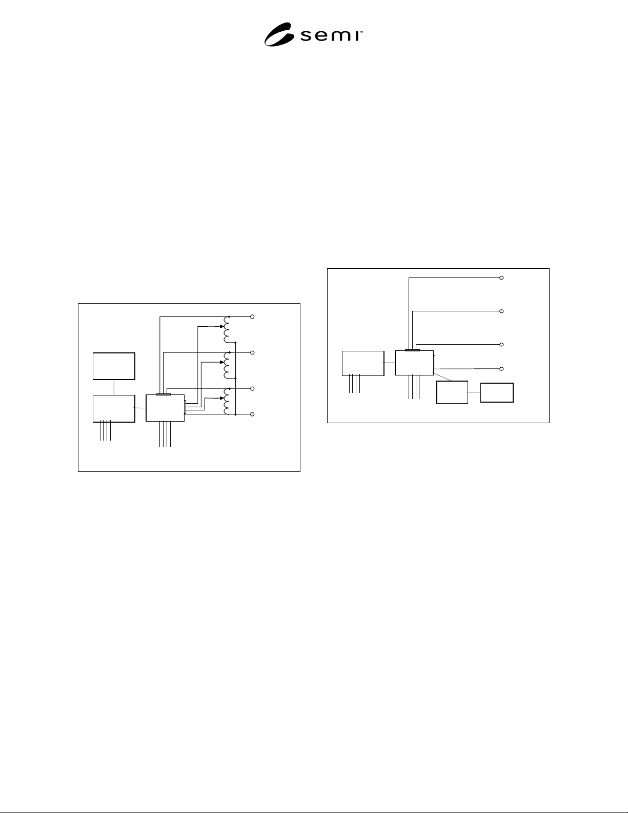
R1-1 Types of Sag Generators
R1-1.1 As defined in the test instrumentation section of
IEC-61000-4-11, there are two common types of
voltage sag generator devices – variable transformer-
switch type and the power amplifier type.
R1-1.2 Both units shown in this section can inject
phase-shifting into the output waveform. All units
except the contactor based transformer-switch type are
capable of some point-on-wave controllability.
Controlle
r
Data Acquisition
And Digital I/O
Solid-state
switches or
contactors
Three-phase
output to load
Nominal
Inpu
t
Variac
Input
Channels
connected
to loa
d
Phase
A
Phase B
Phase
C
N
eutral
Three-phase
utility voltage
Figure R1-1
Transformer-Switch Type Sag Generator
R1-2 Transformer-Switch Type
R1-2.1 This type of sag generator has been built with
either insulated gate bipolar transistor (IGBT), silicon
control rectifier (SCR), or contactors used as the
switching devices. The IGBT based switch is the most
controllable with the ability to precisely control the
point on the waveform in which the voltage sag starts
and finishes (0-360 degrees). With an SCR switch, the
point on wave of the voltage sag starts can be
controlled, but the cutoff point of the voltage sag will
be fixed at zero degrees. In real power systems, the
point-on-wave in which the voltage sag occurs is
somewhat random and unpredictable. A contactor
based unit simulates the randomness of a real power
system in that the point-on-wave in which the voltage
sag begins is not controllable, but is dependent on the
lag time between energizing the coil of the contactor
and contactor closure. Figure R1-1 below displays a
three-phase sag generator test fixture with data
acquisition.
R1-2.2 As shown in Figure R1-1, voltage sags are
injected into the load referenced to the neutral. Since
the three variable transformers shown only need to
carry current during the voltage sag, they do not need to
be rated for continuous current.
Controlle
r
Data Acquisition
& Digital I/O
Power
Amplifier
Three- phase
output to load
Nominal
Input
Channels
connected
to load
Phase
A
Phase B
Phase C
Neutral
Three-phase
Utility voltage
Waveform
Generator
Figure R1-2
Power Amplifier Type Sag Generator
R1-3 Power Amplifier Type
R1-3.1 This type of system utilizes a controller, wave-
form generator, data acquisition systems, and power
amplifier section. Since this type of amplifier can be
highly configurable, it can simulate most any point-on-
wave or phase-shift desired. The power amplifier-
based sag generator will be typically heavier and less
portable than its transformer-switch counterpart. A
conceptual three-phase version of this type of sag
generator test fixture is shown in Figure R1-2.
NOTICE: SEMI makes no warranties or
representations as to the suitability of the test method
set forth herein for any particular application. The
determination of the suitability of the test method is
solely the responsibility of the user. Users are
cautioned to refer to manufacturer’s instructions,
product labels, product data sheets, and other relevant
literature respecting any materials mentioned herein.
These test methods are subject to change without
notice.

SEMI F42-0600 © SEMI 1999, 2000 12
The user’s attention is called to the possibility that
compliance with this test method may require use of
copyrighted material or of an invention covered by
patent rights. By publication of this test method, SEMI
takes no position respecting the validity of any patent
rights or copyrights asserted in connection with any
item mentioned in this test method. Users of this test
method are expressly advised that determination of any
such patent rights or copyrights, and the risk of
infringement of such rights, are entirely their own
responsibility.
Copyright by SEMI® (Semiconductor Equipment and Materials
International), 3081 Zanker Road, San Jose, CA 95134. Reproduction o
f
the contents in whole or in part is forbidden without express written
consent of SEMI.

SEMI F43-0699 © SEMI 19991
SEMI F43-0699
TEST METHOD FOR DETERMINATION OF PARTICLE CONTRIBUTION
BY POINT-OF-USE PURIFIERS
This Test Method was technically approved by the Global Facilities Committee and is the direct
responsibility of the North American Facilities Committee. Current edition approved by the North American
Regional Standards Committee on December 18, 1998. Initially available on www.semi.org February 1999;
to be published June 1999.
1 Purpose
1.1 The purpose of this document is to define a
method for testing POU purifiers intended for
installation into a high-purity gas distribution system
and semiconductor manufacturing process equipment.
Application of this test method is expected to yield
comparable data among POU purifiers tested for the
purposes of qualification for its installation.
2 Scope
2.1 This document describes a test method designed to
draw comparisons of particulate generation
performance of POU purifiers tested under standard
conditions. The procedure utilizes a condensation
nucleus counter (CNC) applied to in-line gas purifiers
typically used in semiconductor applications. It applies
to purifiers of various media and up to 5 cm (~ 2 in.)
i.d. in size and for room temperature operation. The
purifier’s rated flow should be in the range of 0-50
standard liter per minute (slpm). For applications of this
method to larger purifiers, the testing flow rate should be
higher than specified in this method.
2.2 The experimental set up described in this method
can be used for testing either POU purifiers or stand-
alone POU filters.
3 Limitations
3.1 This procedure addresses total particle count
greater than the minimum detection limit (MDL) of the
condensation nucleus particle counter and does not
consider classifying data into various size ranges.
3.2 This methodology specifies flow and mechanical
stress conditions in excess of those considered typical.
These conditions shall not exceed those recommended
by the manufacturer. Actual performance under normal
operating conditions may differ.
3.3 The test medium is limited to nitrogen and argon.
Performance with other gases may vary.
3.4 This method does not include extended particle
count testing or testing under challenging conditions.
3.5 The accuracy of the data generated by this method
is limited to the accuracy of the particle measuring
instruments utilized.
3.6 This method is written with the assumption that
the operator understands the use of the apparatus at a
level equivalent to six months of experience.
4 Referenced Documents
4.1 FED-STD-209. Federal Standard Airborne
Particulate Cleanliness Classes in Cleanrooms and
Clean Zones. General Services Administration.
5 Terminology
5.1 Acronyms
CNC – condensation nucleus counter
DUT – device under test
EP – electropolished
kPa – kiloPascal
LPC – laser particle counter
POU – point of use
psi – pounds per square inch
psia – pounds per square inch absolute
psid – pounds per square inch differential
psig – pounds per square inch guage
Ra – roughness average
Rmax – roughness maximum
scfm – standard cubic feet per minute
slpm – standard liters per minute
5.2 Definitions
5.2.1 background counts — counts contributed by the
test apparatus (including counter electrical noise) with
the spool piece in place of the test object.
5.2.2 CNC — condensation nucleus counter. A light
scattering instrument that detects particles in a gaseous
stream by condensing supersaturated vapor on the
particles.