semi合集-English.pdf - 第893页
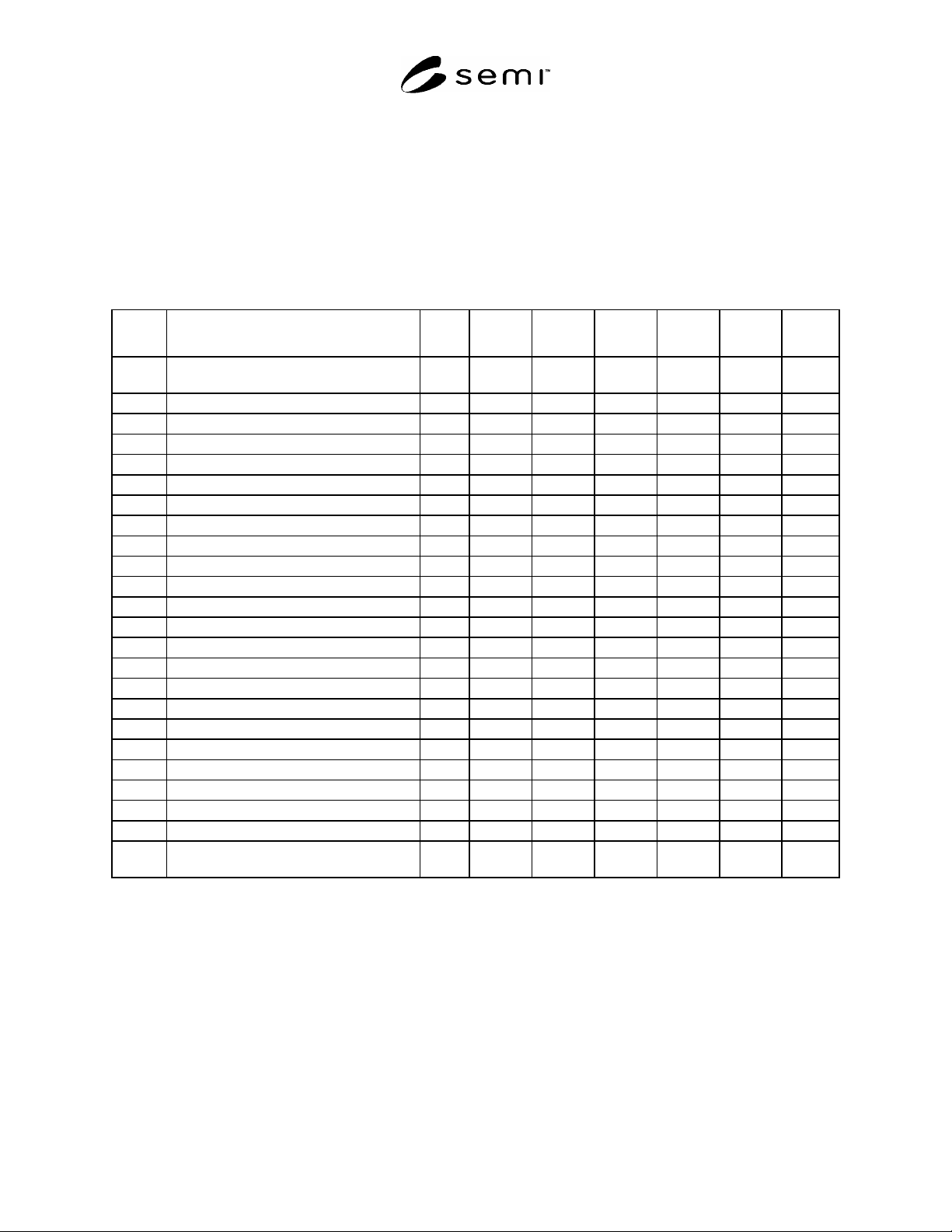
SEMI E116-0705 © SEMI 2002, 2005 25 Table R1-13 Sce nario of Fixed Ty pe Carrier Handling Module Event # Description Time PIO CID-R. X’ fer A X’fer B X’fer C CID-W Opener Map 0 Carrier Handling Module and all components …
SEMI E116-0705 © SEMI 2002, 2005 24
R1-7 Operation Scenarios for Carrier Handling Module
R1-7.1 A couple of following scenarios are typical for different type of Carrier Handling Module.
R1-7.2 Carrier Handling Module for Fixed Buffer Type
R1-7.2.1 Beside the number of Loadports, following table shows just one set of components out of them.
R1-7.2.2 Indicated subsystems: PIO = Carrier Handoff PIO Port, CID-R = Carrier ID Reader, X’fer Transfer
Mechanism = Carrier Transfer Mechanism (Docking Mechanism), CID-W = Carrier ID Writer, Opener = FOUP
Opener, Mapper = Carrier Slot Mapper.
Table R1-12 Scenario of Fixed Type Carrier Handling Module
Event # Description Time PIO CID-R. X’fer
Mech
CID-W Opener Mapper
0 Carrier Handling Module and all
components starting in “IDLE”
0:00 IDLE IDLE IDLE IDLE IDLE IDLE
1 Loading Started 0:30 BUSY
2 Loading Completed 1:00 IDLE
3 ID Reading Started 1:05
BUSY
4 ID Reading Complete 1:10
IDLE
5 ID Verification -
6 Docking Started 1:20
BUSY
7 Docking Complete 1:50
IDLE
8 Opening Start 1:55
BUSY
9 Opening Complete 2:25
IDLE
10 Mapping Started 2:30
BUSY
11 Mapping Complete 2:15
IDLE
12 Slotmap Verification -
13 Process Started 12:15
14 Process Completed 47:15
15 Writing Started 47:20
BUSY
16 Writing Complete 48:10
IDLE
17 Closing Start 48:10
BUSY
18 Closing Complete 48:40
IDLE
19 Undocking Started 48:45
BUSY
20 Undocking Complete 49:15
IDLE
21 Unloading Started 52:25 BUSY
22 Unloading Complete 52:55 IDLE
23 Carrier Handling Module and all
components returning in “IDLE”
52:55
R1-7.3 Carrier Handling Module for Internal Buffer Type
R1-7.3.1 It is assumed that Carrier Slot Mapper and Carrier ID Writer are mounted at an FIMS port next to Internal
Buffer located inside of the equipment. The following table shows the set of components of a single Loadport.
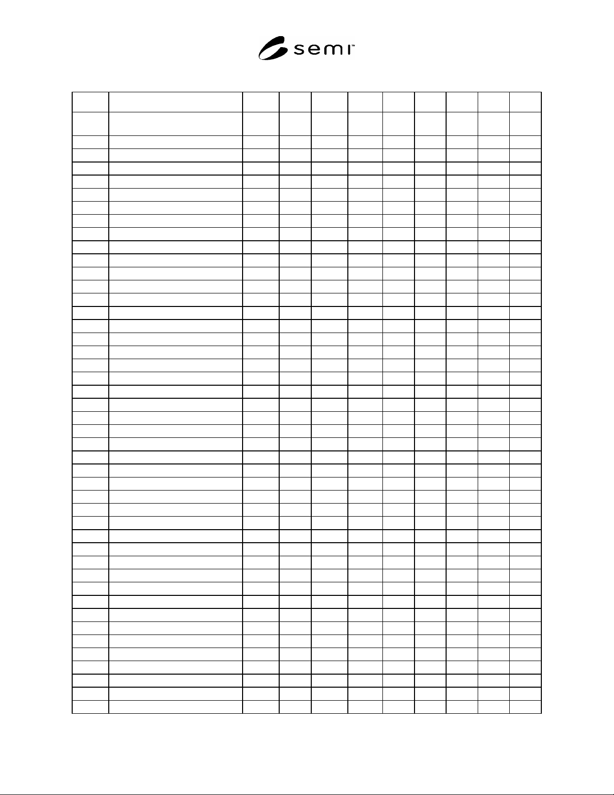
R1-7.3.2 Indicated subsystems: PIO = Carrier Handoff PIO Port, CID-R = Carrier ID Reader, X’fer A = Carrier
Transfer Mechanism from Handoff position to Carrier In/Out position, X’fer B = Carrier Transfer Mechanism of
Internal Buffer, X’fer C = Carrier Transfer Mechanism (Docking Mechanism) for internal FIMS port, CID-W =
Carrier ID Writer, Opener = FOUP Opener, Map = Carrier Slot Mapper
SEMI E116-0705 © SEMI 2002, 2005 25
Table R1-13 Scenario of Fixed Type Carrier Handling Module
Event # Description Time PIO CID-R. X’fer A X’fer B X’fer C CID-W Opener Map
0 Carrier Handling Module and all
components starting in “IDLE”
0:00 IDLE IDLE IDLE IDLE IDLE IDLE IDLE IDLE
1 Loading Started 0:30 BUSY
2 Loading Completed 1:00 IDLE
3 ID Reading Started 1:05
BUSY
4 ID Reading Complete 1:10
IDLE
5 ID Verification -
6 Transfer Started 1:20
BUSY
7 Transfer Complete 1:35
IDLE
8 Moving Started 1:40
BUSY
9 Moving Complete 2:25
IDLE
10 Docking Started 2:30
BUSY
11 Docking Complete 2:50
IDLE
12 Opening Start 2:55
BUSY
13 Opening Complete 3:25
IDLE
14 Mapping Started 3:30
BUSY
15 Mapping Complete 3:15
IDLE
16 Slotmap Verification -
17 Wafer Moving Started 3:30
18 Wafer Moving Completed 7:00
12 Closing Start 7:05
BUSY
13 Closing Complete 7:20
IDLE
21 Undocking Started 7:25
BUSY
22 Undocking Complete 7:45
IDLE
8 Moving Started 7:50
BUSY
9 Moving Complete 8:35
IDLE
17 Process Started 16:15
18 Process Completed 147:15
8 Moving Started 146:30
BUSY
9 Moving Complete 147:15
IDLE
10 Docking Started 147:20
BUSY
11 Docking Complete 147:40
IDLE
19 Writing Started 147:45
BUSY
20 Writing Complete 148:10
IDLE
12 Opening Start 148:10
BUSY
13 Opening Complete 148:25
IDLE
17 Wafer Moving Started 148:30
18 Wafer Moving Completed 152:00
12 Closing Start 152:05
BUSY
13 Closing Complete 152:20
IDLE
21 Undocking Started 152:25
BUSY
22 Undocking Complete 152:45
IDLE
23 Moving Started 152:50
BUSY
24 Moving Complete 153:35
IDLE
25 Transferring Started 153:40
BUSY
26 Transferring Complete 153:55
IDLE

SEMI E116-0705 © SEMI 2002, 2005 26
27 Unloading Started 202:25 BUSY
28 Unloading Complete 202:55 IDLE
29 Carrier Handling Module and all
components returning in “IDLE”
202:55
R1-8 Tracking Performance for Whole Carrier Handling Module
R1-8.1 Even composition and property of equipment are dependent on equipment type, operation and usage
depends on equipment user. Because actual usage deeply affects the whole performance of the Carrier Handling
Module and/or Equipment, the user is responsible for reconstructing the performance from performance tracking
events for each component.
NOTICE: SEMI makes no warranties or representations as to the suitability of the standards set forth herein for any
particular application. The determination of the suitability of the standard is solely the responsibility of the user.
Users are cautioned to refer to manufacturer's instructions, product labels, product data sheets, and other relevant
literature, respecting any materials or equipment mentioned herein. These standards are subject to change without
notice.
By publication of this standard, Semiconductor Equipment and Materials International (SEMI) takes no position
respecting the validity of any patent rights or copyrights asserted in connection with any items mentioned in this
standard. Users of this standard are expressly advised that determination of any such patent rights or copyrights, and
the risk of infringement of such rights are entirely their own responsibility.
Copyright by SEMI® (Semiconductor Equipment and Materials
International), 3081 Zanker Road, San Jose, CA 95134. Reproduction of
the contents in whole or in part is forbidden without express written
consent of SEMI.