semi合集-English.pdf - 第7295页
SEMI MF951-0305 © SEMI 2003, 2005 6 10.1.2 Test Plan B — Three Positions (Center a n d Two E dges, Figure 2): 100 Value Center Value Center Values) Edge of (Avg ROV (2) 10.1.3 Test Plan B1 — Five Positions (Figure …
SEMI MF951-0305 © SEMI 2003, 2005 5
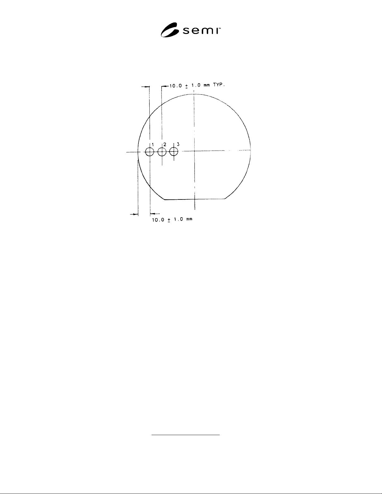
8.4.3 Position spacing shall be in 10 cm steps, center-to-center, continuing to within 5 mm of the sample center.
8.4.4 Position numbering begins at the edge (1) and is sequenced toward the center position.
8.4.5 If a minor flat is located near Position 1, begin sequencing at the opposite edge.
Figure 4
Test Plan D
9 Procedure
9.1 Select one of the test plans defined in §8.
9.2 For referee tests, mark the side of the test slice facing the spectrophotometer infrared source in a noninterfering
manner.
9.3 Place test slice in the fixture apparatus and position in accordance with the selected test plan.
9.4 If the slice thickness is not known for each test site of the selected test plan to ± 0.5% of the nominal slice
thickness, measure the slice thickness at each test site in accordance with SEMI MF533 or DIN 504441/1. Record
the measured or known thicknesses.
9.5 Direct the spectrophotometer infrared beam through the 7 mm aperture located adjacent to the test slice. Move
the test slice, relative to the stationary beam and aperture, to the first test site of the selected plan. Measure and
record the oxygen content at this test site.
9.6 After making the first measurement, move the test slice, relative to the stationary beam and aperture, to the
remaining test sites of the selected plan. Measure and record oxygen content at each test site.
9.6.1 Keep all controllable instrument parameters constant during a test sequence (number of scans, temperature,
reference slice, resolution, etc.).
9.7 For referee tests, repeat the test plan sequence four additional times.
10 Calculations
10.1 Calculate the radial oxygen variation (ROV), in percent, for the sample plan selected:
10.1.1 Test Plan A — Two Positions (Figure 1):
100
ValueCenter
ValueCenter Value Edge
ROV (1)

SEMI MF951-0305 © SEMI 2003, 2005 6
10.1.2 Test Plan B — Three Positions (Center and Two Edges, Figure 2):
100
ValueCenter
ValueCenter Values) Edge of (Avg
ROV (2)
10.1.3 Test Plan B1 — Five Positions (Figure 2):
10.1.3.1 ROV is the larger of the values found from Equation 2 and from the following:
100
ValueCenter
ValueCenter Values) R/2 of (Avg
ROV
(3)
10.1.4 Test Plan C — Five Positions (Figure 3):
100
ValueCenter
ValueCenter Values) Edge of (Avg
ROV
(4)
10.1.5 Test Plan D — Multiple Positions (Figure A1-4):
100
ValueCenter
Value Low IndividualValue)High Individual
ROV
(5)
NOTE 2: All edge positions are located from the center of the IR beam to the slice edge. All other non-center positions are
located such that the center of the IR beam is located as given by the dimensions in Figures 1–4.
10.2 For referee tests, calculate the ROV for each of the five determinations and calculate the average ROV as
follows:
5
54321
ROVROVROVROVROV
ROV
(6)
where ROV
i
is the ROV calculated from the i
th
measurement.
11 Report
11.1 Report the following information:
11.1.1 Date, operator, and affiliation,
11.1.2 Description of test method used,
11.1.3 Number of slices and their identification,
11.1.4 Sample descriptions including nominal resistivity, thickness, diameter, and surface finishes,
11.1.5 Sample plan used,
11.1.6 Instrument factors,
11.1.6.1 Manufacturer/model,
11.1.6.2 Resolution,
11.1.6.3 Apertured beam size,
11.1.6.4 Differential or air reference method,
11.1.6.5 Measurement wavelength region,
11.1.7 ROV results, and
11.1.8 Any unusual relevant conditions.

SEMI MF951-0305 © SEMI 2003, 2005 7
12 Precision
12.1 The test method precision is directly dependent on the precision of the individual oxygen measurements. If the
only sources of precision errors are the individual measurements, the radial oxygen variation precision can be
computed for each sampling plan.
13 Bias
13.1 No reference standards are available for oxygen variation, so it is impossible to determine bias except for that
of the individual measurements. Bias of the individual measurements should be determined in accordance with the
procedures of the test methods utilized.
14 Keywords
infrared transmission; interstitial oxygen; oxygen; radial variation; silicon; uniformity; variation
NOTICE: SEMI makes no warranties or representations as to the suitability of the standards set forth herein for any
particular application. The determination of the suitability of the standard is solely the responsibility of the user.
Users are cautioned to refer to manufacturer's instructions, product labels, product data sheets, and other relevant
literature, respecting any materials or equipment mentioned herein. These standards are subject to change without
notice.
By publication of this standard, Semiconductor Equipment and Materials International (SEMI) takes no position
respecting the validity of any patent rights or copyrights asserted in connection with any items mentioned in this
standard. Users of this standard are expressly advised that determination of any such patent rights or copyrights, and
the risk of infringement of such rights are entirely their own responsibility.
Copyright by SEMI® (Semiconductor Equipment and Materials
International), 3081 Zanker Road, San Jose, CA 95134. Reproduction of
the contents in whole or in part is forbidden without express written
consent of SEMI.