semi合集-English.pdf - 第5122页
SEMI M29-1296 © SEMI 1996, 2003 2 4.1.15 shipping box — a whole co ntainer contai ning a shipping cassette. This is composed of a sh ipping cassette, an outer box, retaine rs, gasket, and clamps. 4.1.16 shipping cassette…

SEMI M29-1296 © SEMI 1996, 2003 1
SEMI M29-1296 (Reapproved 1103)
SPECIFICATION FOR 300 mm SHIPPING BOX
This specification was technically reapproved by the Global Silicon Wafer Committee and is the direct
responsibility of the Japanese Silicon Wafer Committee. Current edition approved by the Japanese Regional
Standards Committee on August 8, 2003. Initially available at www.semi.org September 2003; to be
published November 2003. Originally published December 1996.
1 Purpose
1.1 This specification defines a container for safe
transportation of 300 mm wafers from a wafer maker to
a receiving dock of an IC maker site.
2 Scope
2.1 This specification additionally defines the parts
necessary for a shipping box among cassettes specified
in SEMI E57 and SEMI E1.9, within the range of the
specifications in SEMI E57 and SEMI E1.9.
2.2 This specification also defines the size of a box
containing a shipping cassette containing 300 mm
wafers.
2.3 Although, as for material, use of plastic is a
premise, actual material names are not defined for free
selection based on progress of maker’s technologies.
2.4 Although this specification directs a high-
performance shipping box, this does not concretely
define the performance on particle generation and
sealing capability.
2.5 As for the count of contained wafers, this defines
two sorts, that is, 13 and 25 wafers.
NOTICE: This standard does not purport to address
safety issues, if any, associated with its use. It is the
responsibility of the users of this standard to establish
appropriate safety and health practices and determine
the applicability of regulatory or other limitations prior
to use.
3 Referenced Standards
3.1 SEMI Standards
SEMI E57 — Mechanical Specification for Kinematic
Couplings Used to Align and Support 300 mm Wafer
Carriers
SEMI E1.9 —Mechanical Specification for Cassettes
Used to Transport and Store 300 mm Wafers
NOTICE: Unless otherwise indicated, all documents
cited shall be the latest published versions.
4 Terminology
4.1 Definitions
4.1.1 box bottom — a lower half of an outer box.
4.1.2 box top — an upper half of an outer box.
4.1.3 cassette — a cassette defined in SEMI E57 and
SEMI E1.9.
4.1.4 clamp — a part to fix a box top and a box bottom
mutually.
4.1.5 clamping indent — a groove formed with a box
top and a box bottom. The groove which a clamp hooks
for setting.
4.1.6 front retainer — a retainer which is attached in a
front side of a cassette, the front side which is defined
in SEMI E1.9.
4.1.7 gasket area — an area where gaskets are attached
so as to reduce air flow in a shipping box which is
generated by the difference between internal pressure
and external pressure.
4.1.8 orientation mark — a mark expressed on a part
for confirmation of cassette direction.
4.1.9 outer box — a container part of a shipping box,
surrounding the whole objects so as to protect a
shipping cassette, except gasket and clamps.
4.1.10 poka-yoke — a device applied to a rib so as not
to be set in an incorrect direction in order to avoid an
orientation failure when the part is set.
4.1.11 rear retainer — a retainer which is attached in a
rear side of a cassette, the rear side which is defined in
SEMI E1.9.
4.1.12 retainer — a part to be attached to a shipping
cassette for retaining wafers in transportation so that the
wafers do not move. There are two types, that is, a front
retainer and a rear retainer.
4.1.13 retainer hook — a projection formed on a
shipping cassette for attaching a retainer.
4.1.14 setting hole — a hole formed in a retainer for
attaching the retainer. This makes a pair with a retainer
hook.
SEMI M29-1296 © SEMI 1996, 2003 2
4.1.15 shipping box — a whole container containing a
shipping cassette. This is composed of a shipping
cassette, an outer box, retainers, gasket, and clamps.
4.1.16 shipping cassette — a cassette additionally
defined herein for shipping among cassettes.
4.1.17 stacking rib — a rib formed on a top surface of
a box top and on a bottom surface of a box bottom so as
not to collapse when shipping boxes are stacked. A rib
positioned on the top is called a top rib, and a rib on the
bottom a bottom rib.
4.1.18 supporting rib — a rib inside an outer box for
supporting a cassette.
5 Requirements
5.1 Part Construction — A shipping box defined
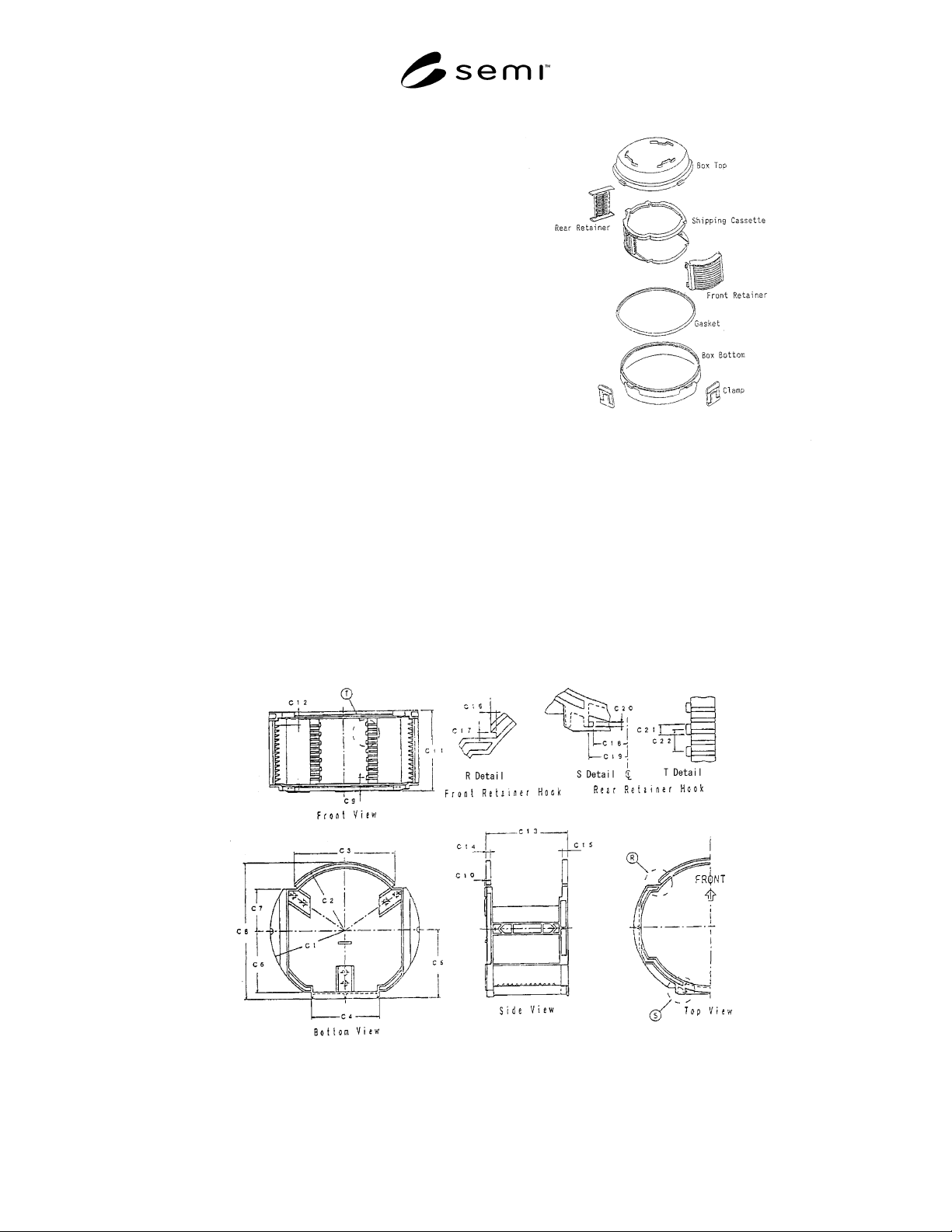
herein is composed of the parts shown in Figure 1.
5.1.1 The appearance of this part is one of
embodiments of this definition.
Figure 1
Components
5.2 Shipping Cassette
5.2.1 Additional Dimensions — Dimensions of a
shipping cassette should conform to SEMI E57 and
SEMI E1.9. However, in the above documents, there
are many Max. or Min. notations, and hence, they are
not sufficient to design a shipping box. Therefore, in
Figure 2 and Table 1, necessary dimensions are added
within the ranges defined in the above documents.
Figure 2
Additional Definition of Shipping Cassette
SEMI M29-1296 © SEMI 1996, 2003 3
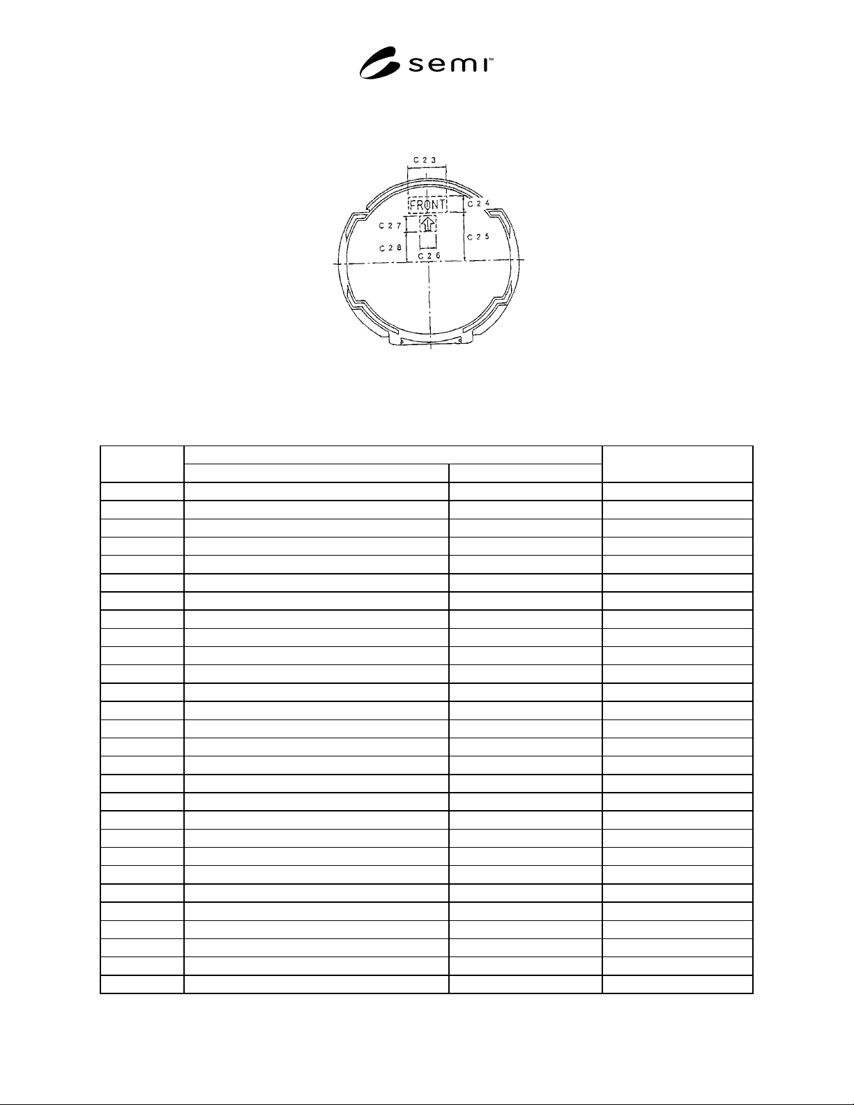
5.2.2 Orientation Mark — The orientation mark indicating the front side of a cassette is shown in Figure 3 and
Table 1. This supports a user to manually set a cassette on a box bottom or a platform of equipment.
Figure 3
Orientation Mark of Shipping Cassette
Table 1 Dimensions of Shipping Cassette
Unit: mm
Standardized Dimension
Location
13 Wafers 25 Wafers
Corresponding to
SEMI E1.9
C1 166 ± 0.5 ← r5
C2 153.5 ± 0.5 ← r6
C3 224 ± 1 ← x6 + x6
C4 152 ± 0.5 ← x5 + x5
C5 155 ± 0.5 ← y16
C6 139.5 ± 0.5 ← y23
C7 94 ± 0.5 ← y15
C8 308.5 ± 1 ← r6 + y16
C9 31 ± 0.5 ← z8 - z1
C10 3 ± 0.5 ←
C11 182 ± 1 302 ± 1.5
C12 29.5 ± 0.5 ← z18
C13 179 ± 3 299 ± 4
C14 10 ± 1 ←
C15 11 ± 1 ←
C16 5 ± 0.5 ←
C17 5 ± 0.5 ←
C18 51 ± 0.5 ← x1
C19 55 ± 0.5 ←
C20 4 ± 0.5 ←
C21 9 ± 0.5 ←
C22 20 ± 0.5 ←
C23 70 ± 10 ←
C24 30 ± 10 ←
C25 90 ± 10 ←
C26 30 ± 10 ←
C27 30 ± 10 ←
C28 55 ± 10 ←