semi合集-English.pdf - 第4856页
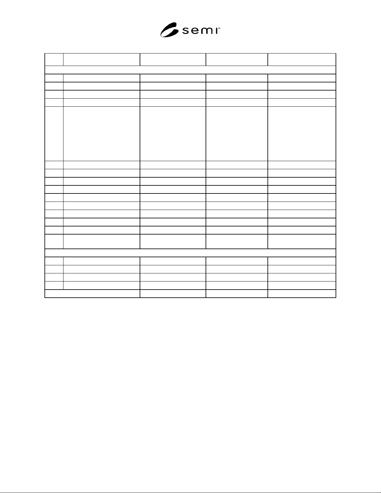
SEMI M1-0305 © SEMI 1978, 2005 32 Table 10 Polished Wafer Defect Limits Item Characteristics Maximum Defect Limit AQL #1 Illumination Conditions #2 FRONT SURFACE 2-8.1 Scratches – Macro #3 None Diffuse 2-8.2 Scratches – …

SEMI M1-0305 © SEMI 1978, 2005 31
6.6.3 Shape — The shape decision tree in Appendix 2 fully describes the various shape parameters that can be
specified.
6.6.3.1 Warp is generally the most often specified shape parameter. Only wafers of category 1.1 (2 in. diameter) do
not have a warp specification. Note that there are two forms of warp, one corrected for gravitational sag and the
other not so corrected.
6.6.3.2 If bow is specified, a sign may be included in the specification to denote convex (positive) or concave
(negative) curvature of the median surface of the wafer with the front surface up. If no sign is included in the
specification, bow may vary between -a and +a, where “a” is the specified maximum magnitude of bow.
6.6.3.3 Sori is an attribute that may be specified with agreement between the supplier and customer in lieu of or in
addition to bow and/or warp.
6.6.4 Standard Wafer Categories — The standardized dimensions, dimensional tolerances, and fiducial (flat or
notch) characteristics for various standard wafer categories are summarized in Tables 4 through 9. These categories
of wafers shall meet all requirements listed in the appropriate table, unless an exception is negotiated between
supplier and customer and is shown on the purchase order.
6.6.4.1 Wafers of the same nominal diameter may typically have different dimensional configurations in different
regions of the world. Many of these configurations are represented in these tables. In selecting the appropriate
standard polished wafer category, consideration should be given to compatibility with processes and equipment
generally available in the region of use.
6.6.5 Flatness — The wafers shall meet global and site flatness requirements as specified in the purchase order.
Details of different flatness parameters are given in Appendix 1.
6.6.6 Nanotopography — The wafers shall meet nanotopography requirements specified in the purchase order.
6.7 Front Surface Chemistry
6.7.1 If surface metal contamination levels are specified on the purchase order, the maximum area densities shall be
designated in units of atoms/cm
2
for specific individual elements together with the measurement method by which
the densities are to be determined. The wafers shall not contain more than the specified density of each metal.
NOTE 3: An example of such a specification applicable to 1 m geometries is given in Related Information 1.
6.7.2 If surface organic contamination levels are specified on the purchase order, the maximum area densities shall
be designated in units of ng/cm
2
for total surface organics density together with the method by which the density is
to be determined. The wafers shall not contain more than the specified density of total surface organics.
6.8 Front and Back Surface Inspection Characteristics
6.8.1 The wafers shall conform to the limits on observable (visually or otherwise) front and back surface
characteristics as specified on the purchase order.
6.8.2 For wafers of diameter 150 mm or smaller for which visual inspection of surface defects is acceptable, the
defect limits in Table 10 may be used as a guide for determining acceptable defect levels. Under these
circumstances, minimal conditions or dimensions for surface features to be considered as defects are stated below.
These limits shall be used for determining wafer acceptability; anomalies smaller than these limits shall not be
considered defects.
6.8.2.1 Item 2-8.1, scratches, macro — Any anomaly conforming to the definition that has a length-to-width ratio
greater than 5:1 and is visible under diffuse illumination as well as under high intensity illumination.
6.8.2.2 Item 2-8.2, scratches, micro — Any anomaly conforming to the definition that has a length-to-width ratio
greater than 5:1 and is visible only under high intensity illumination.
6.8.2.3 Item 2-8.3, pits — Any individually distinguishable nonremovable surface anomaly conforming to the
definition that is visible when viewed under intense illumination.
6.8.2.4 Item 2-8.4, haze — Haze is indicated when the image of a narrow beam tungsten lamp filament is detectable
on the polished wafer surface. Under some conditions, contamination may appear as haze.
SEMI M1-0305 © SEMI 1978, 2005 32
Table 10 Polished Wafer Defect Limits
Item Characteristics Maximum Defect Limit AQL
#1
Illumination Conditions
#2
FRONT SURFACE
2-8.1 Scratches – Macro
#3
None Diffuse
2-8.2 Scratches – Micro
#3
None High Intensity
2-8.3 Pits
#3
None 1.0% Cum. High Intensity
2-8.4 Haze
#3
None 1.0% High Intensity
2-8.5 Localized Light Scatterers (LLS)
(Contamination, Particulate)
#3
Maximum Number
2 in. Diameter Wafer
3 in. Diameter Wafer
100 mm Diameter Wafer
125 mm Diameter Wafer
150 mm Diameter Wafer
4
6
10
10
15
1.0% High Intensity
2-8.6 Contamination, Area
#3
None 1.0% High Intensity or Diffuse
2-8.7 Edge Chips and Indents
#4
None 1.0% Cum. with item 15
#5
Diffuse
2-8.9 Cracks, Crow’s Feet None Diffuse
2-8.10 Craters
#3
None Diffuse
2-8.11 Dimples
#3
None Diffuse
2-8.12 Grooves
#3
None 1.0% Cum. Diffuse
2-8.13 Mounds
#3
None Diffuse
2-8.14 Orange Peel
#3
None Diffuse
2-8.15 Saw Marks
#3
None 1.0% Cum. Diffuse
2-8.16 Resistivity Striations
(Dopant Striation Rings)
None, except on low
resistivity wafers
#6
.
Diffuse
BACK SURFACE
2-9.1 Edge Chips
#4
None 1.0% Cum. with item 6
#5
Diffuse
2-9.3 Cracks, Crow’s Feet None Diffuse
2-9.4 Contamination, Area None 1.0% Cum. Diffuse
2-9.5 Saw Marks
#7
None 1.0% Cum. Diffuse
ALL LISTED CHARACTERISTICS Total 2.5%
#1
Single, Normal, Level II Sampling Plan as defined in ANSI/ASQC Z1.4.
#2
See SEMI MF523 for definition of Illumination Conditions.
#3
The outer 0.062 inch (1.57 mm) annulus is excluded from these criteria.
#4
For wafers that are not mechanically edge-rounded, accept/reject criterion shall be agreed upon between supplier and customer.
#5
The cumulative AQL for both front surface and back surface of wafer is 1.0%.
#6
Striations may be visible on low resistivity wafers (<0.020 ·cm).
#7
For non-lapped wafers accept/reject criterion shall be agreed upon between supplier and customer.
6.8.2.5 Item 2-8.5, localized light scatterers (particulate contamination) — Distinct particles or other surface
anomalies resting on the surface that are revealed under collimated light as bright points.
6.8.2.6 Items 2-8.6 and 2-9.4, area contamination — Any foreign matter on the surface in localized areas that is
revealed under the inspection lighting conditions as discolored, mottled, or cloudy appearance resulting from
smudges, stains, water spots, etc.
6.8.2.7 Items 2-8.7 and 2-9.1, edge chips and indents — Any edge anomaly including saw exit marks conforming to
the definition that is greater than 0.010 in. (0.25 mm) in radial depth and peripheral length.
6.8.2.8 Items 2-8.9a and 2-9.3a, cracks — Any anomaly conforming to the definition that is greater than 0.25 mm
(0.010 in. for 2 and 3 in. diameter wafers) in total length.
SEMI M1-0305 © SEMI 1978, 2005 33
6.8.2.9 Items 2-8.9b and 2-9.3b, crow’s feet—Any anomaly conforming to the definition that is greater than 0.25
mm (0.010 in. for 2 and 3 in. diameter wafers) in total length.
6.8.2.10 Item 2-8.10, craters—Any individually distinguishable surface anomaly conforming to the definition that is
visible when viewed under diffused illumination.
6.8.2.11 Item 2-8.11, dimples—Any smooth surface depression greater than 3 mm in diameter.
6.8.2.12 Item 2-8.12, grooves—Any anomaly conforming to the definition that is greater than 0.13 mm (0.0005 in.
for 2 in. and 3 in. diameter wafers) wide or 0.76 mm (0.030 in. for 2 in. and 3 in. diameter wafers) in length.
6.8.2.13 Item 2-8.13, mounds — Any anomaly conforming to the definition that is greater than 0.25 mm (0.010 in.
for 2 in. and 3 in. diameter wafers) in maximum dimension.
6.8.2.14 Item 2-8.14, orange peel — Any visually detectable roughened surface conforming to the definition that is
observable under diffused illumination.
6.8.2.15 Items 2-8.15 and 2-9.5, saw marks — Any anomaly conforming to the definition that is visible under
diffuse illumination.
6.8.2.16 Item 2-8.16, resistivity striations (dopant striation rings) — Any feature conforming to the definition that
is detectable under diffused lighting conditions.
6.8.3 For other cases, acceptable surface defect levels shall be defined based on the use of surface scanning
inspections systems (SSIS) for automated surface inspection. In this case, definitions of what surface anomalies
constitute surface defects shall be agreed upon between supplier and customer.
7 Basic Specification Requirements
7.1 A basic silicon wafer specification is one that describes a commercially appropriate prime silicon wafer product
having stable quality and parametric control. Wafers procured to this specification for 300 mm diameter, double
side polished silicon wafers shall meet all of the requirements of Table 11 without any change or additional options.
Listed specification values represent generally accepted silicon wafer process capability that is consistent with many
advanced integrated circuit applications at the 130 nm technology level.
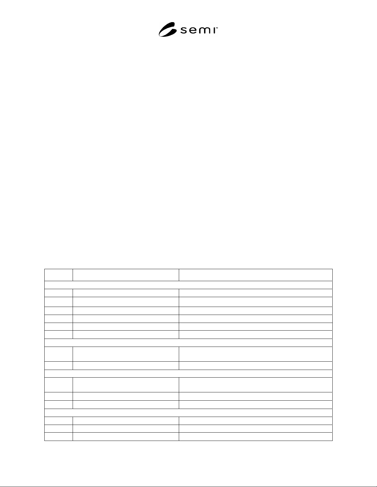
Table 11 Basic Specification for 300 mm Polished Prime Silicon Wafers for the 130 nm Technology Node
Item Specification
2-1. GENERAL CHARACTERISTICS
2-1.1 Growth Method Supplier Option of Cz or MCz
2-1.2
Use of Refined Polysilicon Permitted
2-1.4 Conductivity Type p
2-1.5 Dopant Boron
2-1.6 Nominal Edge Exclusion 3 mm
2-1.8
Wafer Surface Orientation
(100) 0.5
2-2. ELECTRICAL CHARACTERISTICS
2-2.1 Resistivity
Center Point (Target): 1.5 ·cm, 10 ·cm, or 21 ·cm
Resistivity Tolerance: 33%
2-2.2
Radial Resistivity Variation
10% at 6 mm from edge as in SEMI MF81, Sampling Plan B
2-3. CHEMICAL CHARACTERISTICS
2-3.1 Oxygen Concentration
Center Point (target): 15 or 18 ppma ( IOC-88)
Tolerance: 1.5 ppma (IOC-88)
2-3.2
Radial Oxygen Variation
10% at 10 mm from edge as in SEMI MF951, Sampling Plan A1
2-3.3
Carbon Concentration
0.5 ppma (SEMI MF1391)
2-4. STRUCTURAL CHARACTERISTICS
2-4.1 Dislocation Etch Pit Density None
2-4.2 Slip None
2-4.7
Oxidation Induced Stacking Faults
100 cm
2