semi合集-English.pdf - 第4519页
SEMI D25-0600 E © SEMI 2000, 2003 2 • Tak ing into consideration the h ead cl earance when l oading an d unloa ding by forkl ift, as well as the height of the shipping case, th e maximum height of the load is approximate…

SEMI D25-0600
E
© SEMI 2000, 2003 1
SEMI D25-0600
E
SPECIFICATION FOR FLAT PANEL DISPLAY SUBSTRATE SHIPPING
CASE
This specification was technically approved by the Global Flat Panel Display Committee and is the direct
responsibility of the Japanese Flat Panel Display Committee. Current edition approved by the Japanese
Regional Standards Committee on April 21, 2000. Initially available on SEMI OnLine May 2000; to be
published June 2000.
E
This document was editorially modified in October 2003 to correct general editorial errors. Changes were
made to Sections 3.2.2, 6.2.8.1, 6.2.9.1, and A3-1 (figure).
1 Purpose
1.1 This document provides the packing and shipping
specifications and/or guides for FPD glass substrates,
which are called fourth generation substrates (800 ×
950 × 0.7 mm or 800 × 950 × 1.1 mm).
1.2 The objective of this document is to provide cost-
effective packing and shipping in terms of packing
materials, storage, and shipping, while making sure that
packing meets the quality and automation requirements.
2 Scope
2.1 This document defines a specification for a full box
type shipping case (see Figure 2) to be used for packing
and shipping of 4
th
generation FPD glass substrates
from the manufacturer of the glass substrate to the user.
2.2 The application of this packing specification is
limited to the following four FPD glass substrates:
2.2.1 Bare glass substrates which can be used as array
substrates, and do not have film deposition.
2.2.2 Bare glass substrates which can be used as facing
substrates and color filter substrates, and do not have
film deposition.
2.2.3 Array substrates which do have film deposition.
2.2.4 Facing substrates and color filter substrates which
do have film deposition.
2.3 This standard does not purport to address safety
issues, if any, associated with its use. It is the
responsibility of the users of this standard to establish
appropriate safety and health practices and determine
the applicability of regulatory limitations prior to use.
3 Prerequisites and Limitations
3.1 This specification does not apply to:
3.1.1 cassettes used for intra/inter bay transfer inside
the user’s plant;
3.1.2 the semi-separating type the contact type packi-
ng method (see Figure 4) or the full corner supporter
type and the double side supporter type (see Figure 3)
3.2 The premise for glass substrates for this packing
specification is as follows.
3.2.1 Size
W (mm): Short Edge
L (mm): Long Edge
t (mm): Thickness
W = 800 mm W tolerance: see SEMI D24
L = 950 mm L tolerance: see SEMI D24
t = 1.1 t tolerance = see SEMI D24
t = 0.7 t tolerance = see SEMI D24
3.2.2 Squareness — see SEMI D24
3.2.3 Beveling — R beveling
3.2.4 Orientation Corner — see SEMI D24
3.2.5 Corner Cut — see SEMI D24
3.2.6 Edge Exclusion Area — see SEMI D24
3.2.7 Sag — In the event of the glass substrate being
placed horizontally on the support as shown in Figure 1,
sag is defined by h2 (two sides supported), and h4 (four
sides supported) (Unit = mm) (see Figure 1).
3.2.8 Density — Less than 2.8 g/cm
3
3.3 When the glass substrates are shipped, they shall be
loaded vertically.
3.4 When the glass substrates are shipped, a standard
sized pallet shall be used for efficient loading on the
truck platform or the floor of the container (see
Appendices 1 and 2). The standard size used here is less
than 1,100 × 1,100 mm
2
or, at the outside, 1,100 ×
1,200 mm
2
.
3.5 When the glass substrates are shipped, the loading
should be as efficient as possible utilizing the available
space, in line with:
• The smallest height for truck platforms and
containers is 2,300 mm (see Appendices 1 and 2).

SEMI D25-0600
E
© SEMI 2000, 2003 2
• Taking into consideration the head clearance when loading and unloading by forklift, as well as the height of
the shipping case, the maximum height of the load is approximately 2,000 mm. If more efficient loading can be
achieved, multiple boxes can be stacked.
4 Referenced Documents
4.1 SEMI Standards
SEMI D9 — Definitions for Flat Panel Display Substrates
SEMI D11 — Specification for Flat Panel Display Glass Substrate Cassettes
SEMI D24 — Specification for Glass Substrates Used to Manufacture Flat Panel Displays
4.2 JIS Documents
1
JIS D4002 — Internal Dimensions for Rear Body of Motor Trucks
JIS Z0604 — Wooden Flat Pallets
4.3 ISO Documents
2
ISO 668 — Series 1, Freight Container – Classification, Dimensions and Ratings
NOTE 1: As listed or revised, all documents cited shall be the latest publications of adopted standards.
5 Terminology
5.1 Size of exposed portion — The length of the glass substrate exposed from the packing box (full box type) when
the lid of the packing box is open.
6 Packing
6.1 Classification
6.1.1 Classification of packing is as follows:
Packing
Separating type
Semi-separating type
Contact type
Full box type (Figure 2)
Full corner support type (Figure 3, left)
Double side supporter type (Figure 3, right)
Spacer type (Figure 4, top)
Interleaf paper type (Figure 4, down)
Interleaf film type
1 Japan Standards Association, 4-2-24, Minato-ku, Tokyo 107, Japan
2 ISO Central Secretariat, C.P. 56, CH-1211 Geneve 20, Switzerland
SEMI D25-0600
E
© SEMI 2000, 2003 3
6.2 Packing Box Dimensions — Figure 5 shows the key dimensions and tolerances of the packing box for the full
box type.
6.2.1 Packing Box Loading and Unloading
6.2.1.1 Vertical loading shall be used to load and
unload the glass substrates to and from the packing box
(see Figure 6).
6.2.1.2 Vertical loading requires a tall loader/unloader
because of the height of the loading direction. The
ceiling height of the room where the loading equipment
is installed has to be designed accordingly.
6.2.1.3 A suggested method for loading/unloading
substrates from the shipping case with an automatic
vertical loader/unloader is to tilt the box as shown in
Figure 7. Align the substrates on one side of the clear-
ance of the mizo and proceed with loading/unloading.
6.2.1.4 An alternative method for loading/unloading
would be to rotate the packing box 90°, as shown in
Figure 8.
6.2.1.5 Loading and unloading the substrates also can
be done manually without using an automatic
loader/unloader.
6.2.2 Packing Box Size
6.2.2.1 The shorter side of the substrate (side W, or the
800 mm side) as the vertical direction (direction z in
Figure 5) during shipping. This way, the size of the
substrate determines the inside measurements of the
packing box, H: 800 mm (direction z), W: 950 mm
(direction x).
6.2.2.2 The outside measurements of the packing box
shall be H: 980 mm × W: 1,200 mm × L: <
1100mm
(Figure 5). It is important to note that the height of 980
mm indicates that it is possible to stack up the packing
boxes, i.e. 980 mm × 2 = 1,960 mm, and still be less
than the possible maximum height (2,000 mm) of the
truck load.
6.2.2.3 The length of the packing box is determined by
the calculated product of the pitch size between the
substrates times the number of substrates stored in the
box. the length (L in Figure 5) of the packing box
cannot exceed 1,100 mm
6.2.3 Packing Box Lid
6.2.3.1 The packing box must prevent the substrates
from getting contaminated as well as to give pressure to
the substrates for securing them from both top and
bottom. The lid must securely seal and be able to latch
closed to the packing box by a lock. The latching
mechanism must allow easy automatic lock and unlock
as well.
6.2.3.2 The lid shall also have automatic and manual
opening/closing capability. The inside of the lid is
covered with a shock absorber that functions to secure
the glass substrates by pressing them from the top and
bottom.
6.2.4 Mizo Pitch and Capacity of Packing Boxes
6.2.4.1 The sag, h4 = 20 mm will be for the substrates
of the size 800 × 950 × 0.7 mm as shown in Appendix
3, when a sudden turn, acceleration, or braking during
shipping forces a 1G acceleration against the substrates.
From this point of view, the pitch required here is a
little bit larger than 20 mm. However, since all the
substrates in the box are affected by the acceleration at
the same time and in the same direction, the distance
between the substrates will remain constant which
means the substrates should not touch each other.
6.2.4.2 The mizo pitch, must be standardized by each
shipping case supplier, but must range from a minimum
of 9 mm to a maximum of 22 mm ± 0.2 mm. Table 1
shows possible number of substrates per shipping case
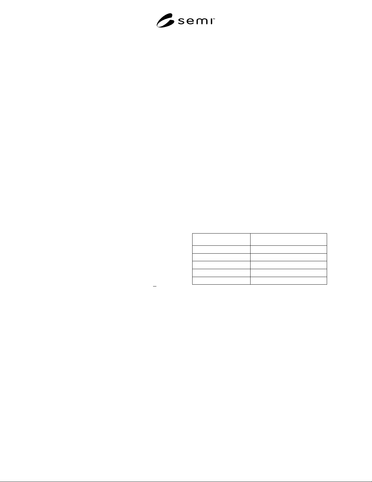
at a given pitch.
Table 1 Pitch and Number of Substrates
Pitch (mm) Number of Substrates (pc)
22 40
18 50
15 60
11 80
9 100
6.2.4.3 The first mizo clearance (see Figure 9) is to be
more than 40.0 mm at the center of the groove. The
distance from the reference plane to the first mizo is the
sum of the first mizo clearance and the thickness of the
side of the box which is the reference plane, and its
allowance is ± 1.0 mm. The allowance of cumulative
pitch distance is less than ± 2.0 mm, and that of each
pitch is less than ± 1.0 mm.
6.2.4.4 Mizo clearance shall be designed to store the
glass substrate of a thickness ranging from 0.7 mm to
1.1 mm.
6.2.5 Size of Exposed Portion
6.2.5.1 In this document, the size of f1 in Figure 10 is
called “the size of the exposed portion” which is set as
f1 = 100 mm. Size h in Figure 10 is the shorter side of
the substrate at 800 mm. The size of f2 is 700 mm
which means one eighth of the whole substrate is
exposed.