semi合集-English.pdf - 第6962页
SEMI S8-0705 © SEMI 1995, 2005 59 Section 10: Workstation Design Section Indicator Figure 10.2.1 Height of keyboard, trackball, or m ouse. (measured to home row and top of ball/mouse). NOTE: In applications where input d…
SEMI S8-0705 © SEMI 1995, 2005 58
Section 10: Workstation Design
Section Indicator Figure
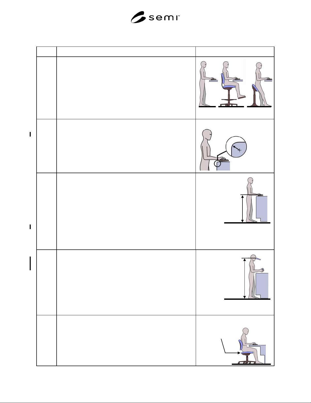
10.1 Standing station (Note A standing station is one where the operator can
assume a standing posture or a seated posture in a tall stool, which places
the operator at approximately the same stature.)
NOTE: If a tall stool, chair or sit/lean stool is used, it is assumed that
the seat is user height-adjustable.
Stand Sit Sit/Lean
10.1.1 Work surface edge radius where the operator can assume a static posture
in contact with the edge.
Acceptance criterion: minimum 6.4 mm (0.25 in.) radius
NOTE: This recommendation applies to both horizontal and vertical
surfaces where the equipment operator can assume a static
posture.
Work surface edge radius
Minimum 6.4 mm
(0.25 in.)
10.1.2 Height of keyboard, trackball, or mouse (to home row, top of ball/mouse).
NOTE: In applications where input devices (keyboard, trackball, or
mouse) are used more like machine controls (intermittent one finger entry
on the keyboard, intermittent short term use of the mouse or trackball)
than for standard typing (continuous use of keyboard for entry of long
character strings, extended use of trackball or mouse in graphical
environment), it is appropriate to use the height and reach locations
described in Section 9, Hand Control Location (standing station).
Acceptance criteria: maximum 1020 mm (40 in.)
minimum 970 mm (38 in.)
NOTE: The home row of a keyboard is the row with the “F” and “J”
typing home keys.
Keyboard, mouse
and trackball height
Maximum 1020 mm
(40 in.)
Minimum 970 mm
(
38 in.
)
10.1.3 Height of microscope eyepieces. Must be adjustable.
Acceptance criterion: Range includes 1270 mm (50 in.) to 1730 mm
(68 in.)
NOTE A: Measured from standing surface to center of the eyepiece.
NOTE B: Both height-adjustable eyepieces and adjustable tables may
be used to meet this recommendation. If a height-adjustable
table is used, the SESC checklist should be used to determine
the appropriate machine load port heights and locations for
displays and controls at the maximum and minimum table
heights.
Maximum 1730 mm
(68 in.)
Minimum 1270 mm
(50 in.)
10.2 Seated station (A seated station where a short cylinder office-style chair is
used.)
NOTE: A height-adjustable chair is assumed.
Height-adjustable,
office style chair
SEMI S8-0705 © SEMI 1995, 2005 59
Section 10: Workstation Design
Section Indicator Figure
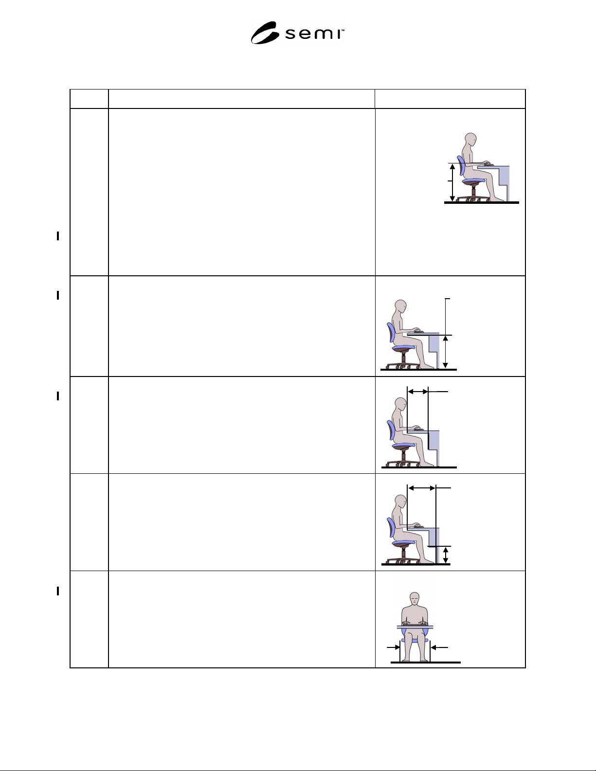
10.2.1 Height of keyboard, trackball, or mouse. (measured to home row and top
of ball/mouse).
NOTE: In applications where input devices (keyboard, trackball, or
mouse) are used more like machine controls (intermittent one finger entry
on the keyboard, intermittent short term use of the mouse or trackball)
than for standard typing (continuous use of keyboard for entry of long
character strings, extended use of trackball or mouse in graphical
environment), it is appropriate to use the height and reach locations
described in Section 9, Hand Control Location (seated station).
Acceptance criteria: maximum 760 mm (30 in.)
minimum 710 mm (28 in.)
NOTE: The home row of a keyboard is the row with the “F” and “J”
keys.
Height of key-
board, track-ball
and mouse
Maximum
760mm
(30 in.)
Minimum
710 mm
(28 in.)
10.2.2 Vertical leg clearance.
Acceptance criterion: minimum 673 mm (26.5 in.)
Vertical leg
clearance
Minimum 673 mm
(
26.5 in.
)
10.2.3 Horizontal leg clearance, depth at knee level.
Acceptance criterion: minimum 508 mm (20 in.)
Horizontal knee
clearance
Minimum 508 mm
(20 in.)
10.2.4 Horizontal leg clearance, depth at foot level.
Acceptance criteria: minimum 660 mm (26 in.) depth × 254 mm (10 in.)
vertical foot clearance.
Horizontal foot
clearance
Minimum 660 mm
(26 in.)
Vertical foot
clearance
Minimum 254 mm
(10 in.)
10.2.5 Horizontal leg clearance: width.
Acceptance criterion: minimum 610 mm (24 in.)
Horizontal leg
clearance, width
Minimum 610 mm
(24 in.)
SEMI S8-0705 © SEMI 1995, 2005 60
Section 10: Workstation Design
Section Indicator Figure
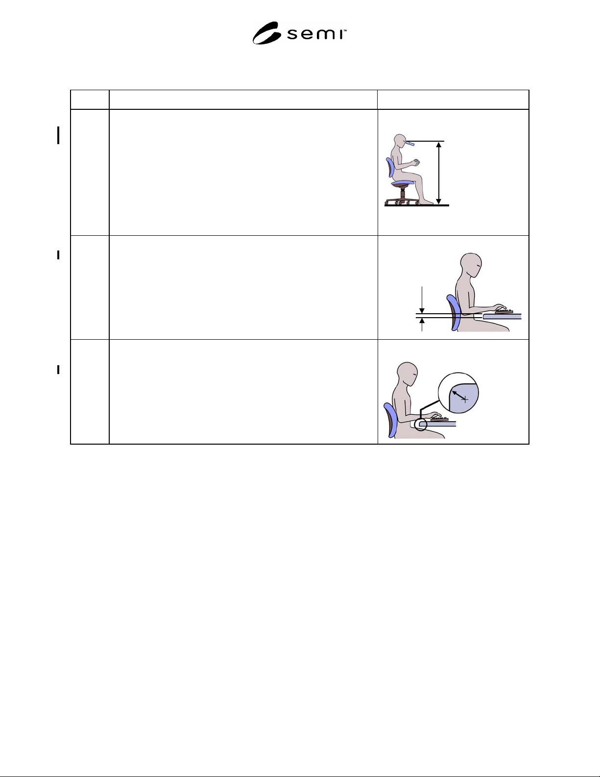
10.2.6 Height of microscope eyepiece. Must be adjustable.
Acceptance criterion: Range includes 1220 mm (48 in.) to 1370 mm
(54 in.)
NOTE A: Measure from the standing surface to center of the eyepiece.
NOTE B: Both height-adjustable eyepieces and adjustable tables may
be used to meet this recommendation. If a height-adjustable
table is used, the SESC checklist should be used to determine
the appropriate machine load port heights, leg clearances, and
the location of controls and displays for the maximum and
minimum table heights.
Microscope
eyepiece heights
Maximum 1370 mm
(54 in.)
Minimum 1220
(48 in.)
10.2.7 Thickness of work surface.
Acceptance criterion: maximum 51 mm (2.0 in.)
Work surface
thickness
Maximum 51
mm
(2.0 in.)
10.2.8 Work surface edge radius where the operator can assume a static posture
in contact with the edge.
Acceptance criterion: minimum 6 mm (0.25 in.) radius
NOTE: This recommendation applies to both horizontal and vertical
surfaces where the equipment operator can assume a static
posture.
Work surface edge radius
Minimum 6.4 mm
(
0.25 in.
)
NOTICE: SEMI makes no warranties or representations as to the suitability of the safety guidelines set forth herein
for any particular application. The determination of the suitability of the safety guidelines is solely the responsibility
of the user. Users are cautioned to refer to manufacturer's instructions, product labels, product data sheets, and other
relevant literature, respecting any materials or equipment mentioned herein. These safety guidelines are subject to
change without notice.
By publication of this safety guideline, Semiconductor Equipment and Materials International (SEMI) takes no
position respecting the validity of any patent rights or copyrights asserted in connection with any item mentioned in
this safety guideline. Users of this guideline are expressly advised that determination of any such patent rights or
copyrights, and the risk of infringement of such rights are entirely their own responsibility.
Copyright by SEMI® (Semiconductor Equipment and Materials
International), 3081 Zanker Road, San Jose, CA 95134. Reproduction of
the contents in whole or in part is forbidden without express written
consent of SEMI.