semi合集-English.pdf - 第6317页
SEMI G62-95 © SEMI 1995, 2002 2 5.11 discolorat ion — Any ch ange in the color of the metallization , as detected by the naked eye. This may occur on as plated or af ter application of heat. 5.12 excessive plating — Plat…
SEMI G62-95 © SEMI 1995, 2002 1
SEMI G62-95 (Reapproved 0302)
TEST METHOD FOR SILVER PLATING QUALITY
This test method was technically appoved by the Global Physical Interfaces and Carriers Committee and is
the direct responsibility of the Japanese Physical Interfaces and Carriers Committee. Current edition
approved by the Japanese Regional Standard Committee on November 26, 2001. Initially available at
www.semi.org December 2001; to be published March 2002. Originally published in 1995.
1 Purpose
1.1 This test method describes procedures to determine
silver plating quality.
2 Scope
2.1 These methods apply to silver plating on
leadframes for plastic packages. Applicable plating
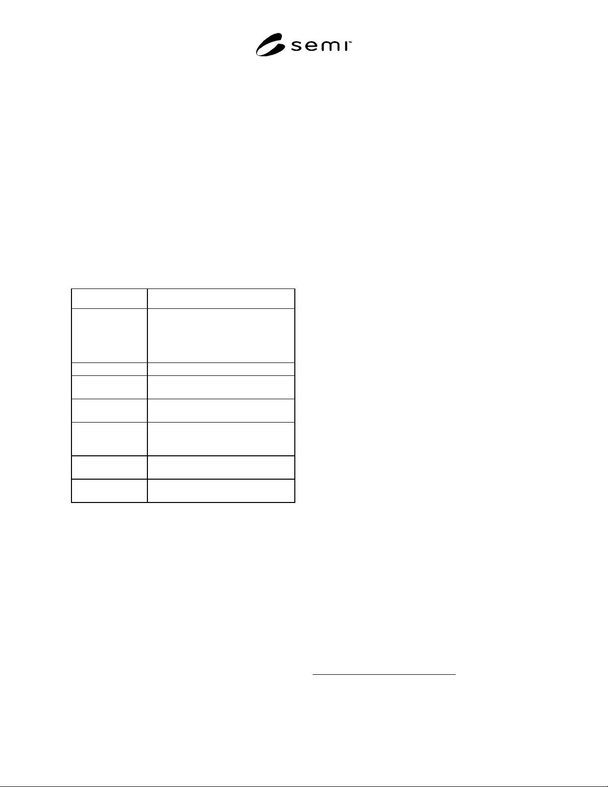
styles are listed in Table 1.
Table 1 Plating Style
Plating Style Description
Overall Plating Plating covers the whole leadframe
area. In some situations, the leadframe
may be quoted as having overall plating,
but the rails will be unplated in order to
save plating costs.
Ring Plating Only inner leads plated on top surface.
Ring-Tip Plating Only wire bonding areas of inner leads
plated.
Spot Plating Only die pad and inner leads plated on
top surface.
Spot Plating (both
sides)
Die pad and inner leads are plated on
both the top and bottom surfaces of the
leadframe.
Tip Plating Only die pad and wire bonding areas
plated.
W-Ring Plating Only inner leads plated on top surface
and around die pad.
2.2 This standard does not purport to address safety
issues, if any, associated with its use. It is the
responsibility of the users of this standard to establish
appropriate safety health practices and determine the
applicability or regulatory limitations prior to use.
3 Units
3.1 This test method uses SI units.
4 Referenced Standards
4.1 SEMI Documents
SEMI G55 — Test Method for Measurement of Silver
Plating Brightness
SEMI G56 — Test Method for Measurement of Silver
Plating Thickness
4.2 Military Specifications
1
MIL-M-38510 — General Specification for
Microcircuits
5 Terminology
5.1 area variation — The variation between the
defined and actual plated area.
NOTE 1: Oversized plating area is an area larger than the
specified area. Undersized plating area is an area smaller than
the specified area.
5.2 attached silver particles — Small silver particles
which are attached to the normal plated surface during
the plating process.
5.3 bleed out, back side — Plating on the back of
leadframe caused by seepage of the plating solution
beyond the mask.
5.4 bleed out, side — Plating occurring on the sides of
leadframe features.
5.5 bleed out, surface — Seepage of the plating
solution beyond the mask on the top surface of the
leadframe increasing the plated area.
5.6 bleed out, epoxy — The separation of the resin
component from the filled epoxy resin such that it
creeps on the die pad beyond the outline of resin fillet.
5.7 blister (metal) — An enclosed, localized separation
of the plating metallization from the base material or
from another layer of plating which can be depressed
with a sharp instrument.
NOTE 2: This may occur during plating or after application of
heat.
5.8 burnt deposit — Plated surface is too rough.
5.9 contamination — Three-dimensional alien material
adhering to a surface.
5.10 corrosion — Electrochemical degradation of the
material usually exhibited by discoloration such as rust.
1 Available through the Naval Publications and Forms Center, 5801
Tabor Avenue, Philadelphia, PA 19120-5099, USA. Telephone:
215.697.3321

SEMI G62-95 © SEMI 1995, 2002 2
5.11 discoloration — Any change in the color of the
metallization, as detected by the naked eye. This may
occur on as plated or after application of heat.
5.12 excessive plating — Plating exists outside the
specified area.
5.13 foreign material — An adherent particle other
than parent material of the component.
NOTE 3: Adherent denotes inability to be removed with an
air or nitrogen blow-off at 20 psi.
5.14 incomplete plating — Plating is missing from any
part of the designated area.
5.15 leadframe top surface — The active side of the
leadframe, the surface used for die attach and wire
bonding.
5.16 nodule (of plated particle) — A protrusion or
lump of plating material above the plated surface.
5.17 plating nonuniformity — The lack of consistency
of brightness of silver as plated, or after the application
of heat. These changes in the plated grain structure
causes the inconsistency.
5.18 peeling — The lifting of metallization from a
surface.
5.19 pit (of plating) — A hole or depression extending
below the surface of the plating.
5.20 scratch (on plating) — A surface deformation
which exposes underlying metallization.
5.21 spot-sparing — A stain-like discoloration
occurring after the application of heat.
5.22 step plating — Plateau-like plating having more
than one level.
5.23 spot plating misalignment — The variation
between the defined and actual center lines of the plated
area.
5.24 tape test — A metallization layer adhesion test
technique using adhesive tape to apply a peel force to
the layer. This test may be applied on plated material or
after the application of heat.
5.25 whisker — A plating metal burr-like filament
attached to the surface of the plating.
6 Summary of Method
6.1 Various test methods are described or referenced to
determine silver plating quality for the following items:
• Plating Area
• Plating Thickness
• Plating Brightness
• Visual Inspection
• Functional Test
7 Interferences
7.1 Avoid contaminating the silver plated surface prior
to performing the test. Such contamination may affect
visual appearance and die attach, wire bonding, and
solderability functional tests.
8 Equipment
8.1 GAM densitometer or equivalent
8.2 X-Ray Fluorescence
8.3 Microscope with a 40× maximum magnification.
8.4 Heater block, hot plate or oven (furnace)
9 Sampling
9.1 Sampling plans shall be agreed between user and
supplier.
10 Test Sequence
10.1 When the test methods are used at incoming
inspection, the sequence of tests shall be as follows:
10.1.1 Plating Area — See Section 11.1.
10.1.2 Plating Thickness — See Section 11.2.
10.1.3 Plating Brightness — See Section 11.3.
10.1.4 Visual Inspection — See Section 11.4.
10.1.5 Heat Test — See Section 11.5.
10.1.6 Functional Test — See Section 11.6.
11 Test Procedures
11.1 Plating Area
11.1.1 Measurements may be made by using a glass
scale, shadow scope, or microscope.
11.1.2 Measurement items are listed below:
11.1.2.1 Area variation
11.1.2.2 Spot plating misalignment
11.2 Plating Thickness
11.2.1 Plating thickness shall be measured at a point on
the inner lead or the center point of the die pad.
NOTE 4: The location of the thickness test shall be agreed
between user and supplier.
11.2.2 Thickness measurements may be made using X-
Ray Fluorescence per SEMI G56.
11.3 Plating Brightness

SEMI G62-95 © SEMI 1995, 2002 3
11.3.1 Plating brightness shall be measured at the
center point of the die pad.
NOTE 5: If leadframes do not have a plated die pad, the
location of the brightness test shall be agreed between user
and supplier.
Plating brightness shall be measured using a GAM
densitometer or equivalent per SEMI G55.
11.4 Visual Inspection
11.4.1 Visual inspection may be performed with the
naked eye or a microscope with up to 40× maximum
magnification, as required to confirm results.
11.4.2 Visual inspection shall be performed before and
after functional testing.
11.4.3 Inspection items are listed below.
1. attached silver particles
2. blister
3. bleed-out
4. burnt deposit
5. contamination
6. corrosion
7. discoloration
8. excessive plating
9. foreign material
10. incomplete plating
11. nodule
12. plating nonuniformity
13. peeling
14. pit
15. scratch
16. spot-sparing
17. step plating
18. whisker
11.5 Heat Test
11.5.1 Conditions — The conditions in Table 2 shall be
used to heat test silver plated leadframes.
Table 2 Heat Test Condition
Leadframe Material Bake Temperature Bake Time (min.)
Iron-Nickel Alloy
per MIL-STD-
38510, Type B
400° C ± 5° C 3 min. + 10 (-0) sec.
Cu Alloy 300° C ± 5° C 3 min. + 10 (-0) sec.
Taped Leadframe 275° C ± 5° C 3 min. + 10 (-0) sec.
11.5.2 The test may be carried out on a heater block or
hot plate, or in an oven (furnace). The heat capacity of
the test equipment must be sufficient to avoid
temperature swings outside the specified limits when
the test is started.
NOTE 6: When using a heater block or hot plate, ensure that
air flow does not affect the bake temperature.
11.6 Functional Test
11.6.1 Epoxy Die Bonding — Processes and test
procedures shall be agreed upon between user and
supplier.
11.6.2 Gold Wire Bonding — Processes and test
procedures shall be agreed upon between user and
supplier.
11.6.3 Solderability — Processes and test procedures
shall be agreed upon between user and supplier.
12 Related Documents
12.1 SEMI Specifications
SEMI G8 — Test Method for Gold Plating Quality
SEMI G21 — Specification Plating Integrated Circuit
Leadframes
12.2 JIS Specifications
2
JIS H8501 — Methods of Thickness Test for Metallic
Coatings
JIS H8621 — Electroplated Coatings of Silver for
Engineering Purpose
JIS Z8722 — Methods of Measurement for Color of
Reflecting or Transmitting Objects
JIS Z8741 — Method of Measurement for Specular
Glossiness
NOTICE: SEMI makes no warranties or
representations as to the suitability of the standards set
2 Japanese Industrial Standards, Available through the Japanese
Standards Association, 1-24, Akasaka 4-Chome, Minato-ku, Tokyo
107-8440, Japan. Telephone: 81.3.3583.8005; Fax: 81.3.3586.2014
Website: www.jsa.or.jp