semi合集-English.pdf - 第7722页
SEMI T12-0305 © SEMI 2004, 2005 1 SEMI T12-0305 SPECIFICATION FOR TRACING JIGS AND IMPLEMENTS This specificati on was technically approved by the Global Trac eability Committee and is the direct responsibility of the Jap…
SEMI T11-0703 © SEMI 2002, 2003 6
RELATED INFORMATION 1
OTHER CONSIDERATIONS
NOTICE: This related information is not an official part of SEMI T11. It was derived from task force discussions
and is provided for reference and information only. This related information was approved for publication by full
letter ballot on August 29, 2002.
R1-1 Other Considerations
R1-1.1 This specification defines only the location of
the ID mark on the reticle surface. However, issues
relating to substrate edge length tolerances, pellicles,
reticle positioning, robotic end effectors and alignment
marks were considered in development of the
specification. These are summarized below and in
Figure R1-1.
R1-1.2 Substrate Edge Length — Table 1 of SEMI P1
specifies that edge length for 6” reticle substrates shall
be ≥ 151.6 mm and ≤ 152.4 mm. Figure 2 represents
this as 152.0 ± 0.4 mm.
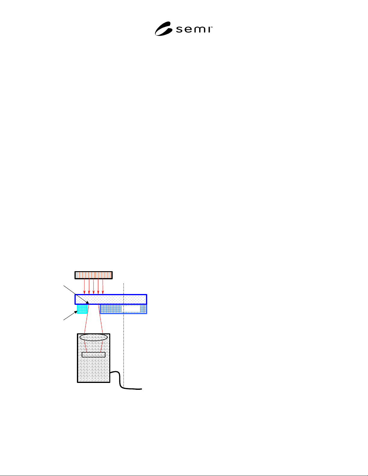
R1-1.3 Pellicles — It is assumed that the pellicle is a
square with a nominal size of 124 mm that is centered
on the mask substrate. A pellicle misalignment
allowance of ± 0.5 mm has been suggested by reticle
suppliers and users; this is reflected in Figure 3. An
unpatterened chrome film is specified between the quiet
zone and pellicle frame to eliminate influence on the
reader of light scattered from the pellicle frame when
mark reading illumination and the reader camera are on
opposite sides of the reticle as shown in Figure R1-1.
Effector End
Illuminator
CCD
Camera
Symbol
Pellicle
Reticle
Controller &
Decoder
Figure R1-1
Example of Top-Side ID Illumination with Pattern-
Side Reader and End Effector
R1-1.4 Reticle Positioning — Misalignment in a tool
can result from several factors, e.g. position in the
cassette, position on the end effector, substrate
squareness and others. A reticle misaligment allowance
of ± 1.5 mm has been suggested by stepper and other
tool suppliers and users. This is reflected in Figure 3.
R1-1.5 Robotic End Effectors — End effector grips are
typically ≤ 6.0 mm wide, in the reticle contact area. A
6.0 mm end effector width is shown in Figure 3.
NOTICE: SEMI makes no warranties or
representations as to the suitability of the standards set
forth herein for any particular application. The
determination of the suitability of the standard is solely
the responsibility of the user. Users are cautioned to
refer to manufacturer' s instructions, product labels,
product data sheets, and other relevant literature
respecting any materials mentioned herein. These
standards are subject to change without notice.
The user’s attention is called to the possibility that
compliance with this standard may require the use of
copyrighted material or of an invention covered by
patent rights. RVSI Acuity CiMatrix has filed a
statement with SEMI asserting that the patented or
copyrighted item can be used by the public for the
purpose of implementing this standard without specific
license and without payment of royalty or other charge.
Attention is also drawn to the possibility that some
elements of this standard may be subject to patented
technology or copyrighted items other than those
identified above. Semiconductor Equipment and
Materials International (SEMI) shall not be held
responsible for identifying any or all such patented
technology or copyrighted items. By publication of this
standard, SEMI takes no position respecting the validity
of any patent rights or copyrights asserted in connection
with any item mentioned in this standard. Users of this
standard are expressly advised that determination of
any such patent rights or copyrights and the risk of
infringement of such rights are entirely their own
responsibility.
Copyright by SEMI® (Semiconductor Equipment and Materials
International), 3081 Zanker Road, San Jose, CA 95134. Reproduction o
f
the contents in whole or in part is forbidden without express written
consent of SEMI.

SEMI T12-0305 © SEMI 2004, 2005 1
SEMI T12-0305
SPECIFICATION FOR TRACING JIGS AND IMPLEMENTS
This specification was technically approved by the Global Traceability Committee and is the direct
responsibility of the Japanese Traceability Committee. Current edition approved by the Japanese Regional
Standards Committee on November 24, 2004. Initially available at www.semi.org January 2005; to be
published March 2005. Originally published in 2004; previously published July 2004.
1 Purpose
1.1 Semiconductor production equipment may use jigs and/or implements to produce semiconductor devices. Some
case such important conditions as quality of products and tool performance may depend on jigs or implements. This
difference often comes from such historical events as processing cycles, processing products, stocking environment.
To make sure correlation between the conditions and the events tracing jigs and implements is required.
1.2 Purpose of this document is to establish concept to trace jigs and/or implements used on equipment for
processing material and make sure required information, communications and services to realize the concept.
2 Scope
2.1 Scope of this specification includes management of required information on equipment. Because a specific
piece of jig may be used on other equipment, usually same type and/or same supplier, information transfer between
equipment and factory host computer is also in the scope of this specification.
2.2 Such physical issues mark position and mark readers are out of scope, for this specification treats just tracing
information, communication of it and logical management. The physical specification may be standardized
separately.
2.3 As long as management on this specification and above requirement is expected on an equipment, the
equipment is in the scope regardless of the type of process or type of equipment.
2.4 But if jigs and/or implements for certain type of equipment have been already traced or managed complying
with existing standard or along with some specification conventionally, they are out of scope of this specification.
But this specification can be applied even to such jigs and tools if user and/or suppliers want.
2.5 Because this specification describes just base functionalities to realize the traceability, applications of the
functionalities including checking or management of counterfeits are out of scope.
NOTICE: This standard does not purport to address safety issues, if any, associated with its use. It is the
responsibility of the users of this standard to establish appropriate safety and health practices and determine the
applicability of regulatory or other limitations prior to use.
3 Limitations
3.1 This specification defines and makes sure concept and information transfer basics. Specification about physical
ID marking on jigs and tools including readers/writers, and such application of this tracking as security and
operations are dependent to standard users. They are responsible for their application and related regal issues.
4 Referenced Standards
4.1 SEMI Standards
SEMI E5 — SEMI Equipment Communications Standard 2 Message Content (SECS-II)
SEMI E30 — Generic Model for Communications and Control of Manufacturing Equipment (GEM)
SEMI E39 — Object Service Standard: Concepts, Behavior, and Services
NOTICE: Unless otherwise indicated, all documents cited shall be the latest published versions.
SEMI T12-0305 © SEMI 2004, 2005 2
5 Terminology
5.1 Definitions
5.1.1 Attachment — general term of Jig and Implement.
5.1.2 Implement — a kind of Attachment used to assemble/maintain/improve measurement or production
equipment.
5.1.3 Jig — a kind of Attachment used to support measurement or production for material on one or more
equipment.
6 Convention
6.1 This section defines the conventions followed by this document.
6.2 Object Conventions — This document conforms to the conventions for objects established by SEMI E39,
including object diagrams, object terminology, and re-quirements for standardized objects. Accordingly, notation is
based on Unified Modeling Language (UML).
6.2.1 Formal Name of an Object — The text capitalizes formal object name references. Similar to the way
capitalization is normally used when discussing entities. When describing something in the general (like cities)
lower case is used, but when a specific entity is of interest (New York City), then first letters are capitalized.
6.2.2 Components of Complex Attributes — The names of object attributes defined in tables are left-justified. The
individual elements of complex attributes are right-justified in order of appearance below the complex attribute.
6.3 State Model Conventions
6.3.1 This document uses the Harel state chart convention for describing dynamic operation of defined objects. The
outline of this convention is described in an attachment of SEMI E30. The official definition of this convention is
described in “State charts: A Visual Formalism for Complex Systems”
1
.
6.3.2 The Harel convention has not the concept of state models of “creation” and “extinction” for expressing a
temporary entity. The Secondent described in this document is such an entity, and a copy of the same state model is
used for an independent job newly created. In this document, a circle with a black circle inside is used for
expressing extinction of an entity. A filled black circle denotes the entry to the state model (the entity creation).
6.3.3 Transition tables are provided in conjunction with the state diagrams to explicitly describe the nature of each
state transition. A transition table contains columns for Transition number, Previous State, Trigger, New State,
Actions, and Comments. The “trigger” (column 3) for the transition occurs while in the “previous” state. The
“actions” (column 5) includes a combination of:
1. Actions taken upon exit of the previous state.
2. Actions taken upon entry of the new state.
3. Actions taken which are most closely associated with the transition.
4. No differentiation is made between these cases.
Num Previous State Trigger New State Actions Comments
6.4 Service Message Representation — Services are functions or methods that may be provided by either the
equipment or the host. A service message may be either a request message, which always requires a response, or a
notification message, that does not require a response.
1 D. Harel, “State charts: A Visual Formalism for Complex Systems”, Science of Computer Programming 8, 1987.