semi合集-English.pdf - 第7492页
SEMI MF1708-1104 © SEMI 2004 4 8.7 Deionized ( DI) Water — Electronic grade Type E-2 as described i n ASTM Guide D 512 7 . 8.8 Silicon Pedestals — 6 mm by 6 m m by 100 mm single crystalline silicon cu t from high purity …
SEMI MF1708-1104 © SEMI 2004 3
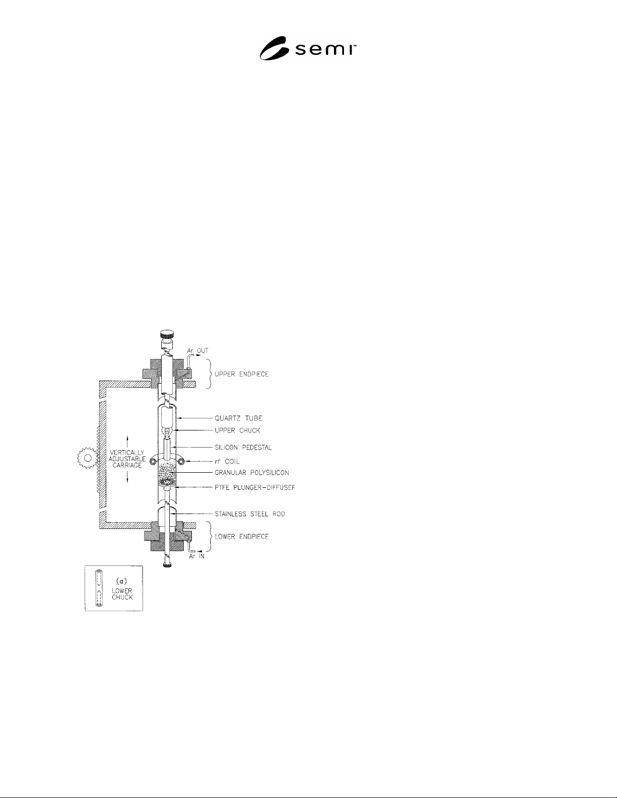
7.6 Melter/Float Zone Apparatus — A radio frequency
(rf) generator operating between 2.0 and 3.0 MHz with
a copper, water-cooled working coil for rf coupling to
the silicon (see Figure 1). The coil shall have an inside
diameter of 20 mm to accommodate the 18 mm outside
diameter quartz tube and shall have sufficient power to
sustain a molten zone of at least 2 cm. Controls to
adjust the power output of the rf generator must be
readily available to the operator. The apparatus shall
have a carriage to vertically support and move the
quartz tube through the coil in a smooth and continuous
manner. The upper and lower endpieces of the carriage
shall be designed with chucks to hold silicon pedestals
as well as the quartz tubing. These endpieces shall
provide a seal to exclude air from the inside of the tube
and have connections for argon entry at the bottom
endpiece and exhaust at the top. Manual as well as
motorized movement of the carriage in the vertical
direction while minimizing horizontal motion is
essential. This entire apparatus is set up and utilized
inside a Class 6 clean room.
Figure 1
Melter/Float Zone Apparatus
7.7 PTFE Plunger-Diffuser — A cylindrical piece of
PTFE machined to close tolerance that fits snugly but
can be moved freely inside the quartz tube. This PTFE
plunger is drilled with an array of small holes for
diffusion of argon gas from the bottom endpiece of the
zoner carriage, through a bed of polysilicon granules,
and finally exhausted through the top endpiece. The
bottom of this plunger is machined to fit on the end of a
stainless steel rod that is extended through and
supported by the bottom endpiece. This rod provides a
way to vertically move the PTFE plunger/diffuser plate
within the quartz tube.
7.8 Chucks — Designed to hold silicon pedestals and
seed rods.
7.8.1 Upper Chuck — A three-jaw chuck designed to
hold a 6-mm silicon pedestal rod inside the quartz tube
and supported vertically from the top carriage piece.
7.8.2 Lower Chuck — A cylindrical piece of stainless
steel that fits inside the quartz and upon the upper end
of the stainless steel rod extending from the lower
endpiece with a hole drilled in the top about 3 mm
inside diameter and 1 cm deep (see Figure 1). This
supports a 2.5 mm single crystal silicon seed rod in a
near vertical position while allowing some (about 2
mm) horizontal movement at the top of an 80 mm rod.
7.9 Hydrogen Torch — Constructed by restricting the
end of a
¼ in. outside diameter piece of stainless steel
tubing and drilling a 1.5 mm hole as the orifice. This
torch is used to preheat the silicon to the point where rf
coupling occurs.
7.10 Diamond Saw — Suitable for cutting a sample 2 to
4 mm thick from the single crystal ingot.
7.11 Clean Room Garb — Including gowns, gloves, lint
free paper, etc.
7.12 Polyethylene Forceps — Size to hold 6 to 12-mm
silicon slice.
7.13 PTFE Beakers — 100 mL in size for handling
acids used in etching or cleaning.
8 Reagents and Materials
8.1 Hydrogen Gas — Low purity gas cylinder for
hydrogen torch.
8.2 Argon Gas — In accordance with SEMI C3.42.
8.3 Hydrofluoric (HF) Acid (49 %), in accordance with
Grade 1 of SEMI C28.
8.4 Nitric (HNO
3
) Acid (70 %) — In accordance with
Grade 1 of SEMI C35.
8.5 Mixed Acid Etchant (MAE) 57:18:25 — Composed
of HF:HNO
3
:Acetic Acid, in accordance with Grade 1
of SEMI C34.
8.6 Methanol — In accordance with Grade 1 of SEMI
C31.

SEMI MF1708-1104 © SEMI 2004 4
8.7 Deionized (DI) Water — Electronic grade Type E-2
as described in ASTM Guide D 5127.
8.8 Silicon Pedestals — 6 mm by 6 mm by 100 mm
single crystalline silicon cut from high purity silicon
ingots.
8.9 Silicon Seed Rod — 2.5 mm by 2.5 mm by 100 mm
single crystal <100> silicon rod cut from high purity
<100> silicon ingot.
9 Hazards
9.1 The acids used in this practice are potentially
harmful and must be handled with the utmost of care at
all times. Hydrofluoric acid (HF) solutions are
especially hazardous to the eyes, skin, mucous
membranes, and the lungs. Anyone using HF and other
acids must be familiar with the potential hazards and
must employ proper techniques and preventive
measures to avoid injury.
9.2 The rf generator and coil of the melter-zoner
apparatus can be injurious to the operator if the operator
is not properly trained in working with electrical
connections, rf fields, and hot parts.
9.3 Use eye protection to protect the operator from the
bright light of the molten silicon in the melter-zoner
apparatus.
10 Sampling
10.1 Granular polysilicon samples are best handled in
clean, dry quartz bottles. Samples are always taken
with clean silicon or quartz scoops or devices.
10.2 Granular polysilicon is commercially produced by
a continuous process in a fluidized bed reactor.
Samples for evaluation by this practice can be taken in
process, while packaging (normally in 270–300 kg
specially lined drums), or at the point of use. The
sampling point is therefore determined by the purpose
of the evaluation.
11 Reference Specimen
11.1 Use a large homogeneous sample of granular
polysilicon reference material to monitor the process of
consolidation and conversion to a single crystal silicon.
Periodically and repeatedly convert this reference
material to single crystal silicon to establish the
consistency and cleanliness of this practice.
11.2 Collect and statistically evaluate the values
obtained by low-temperature Fourier transform infrared
spectroscopy for carbon and the acceptor and donor
impurities in the analytical slices to establish and keep
the process in control.
12 Preparation of Apparatus
12.1 Take the utmost care to ensure the cleanliness of
all parts of the melter/zoner, especially the quartz tube,
sample containers, transfer funnel, and the carriage
endpieces.
12.1.1 Clean the inner part of the quartz tube and etch
it with 3:1 HF:HNO
3
. Following the acid etch, rinse the
tube with copious amounts of DI water and allow it to
dry in a laminar air flow hood.
12.1.1.1 Warning: Acids, especially HF, are very
hazardous to the eyes, skin, mucous membranes, and
lungs. Anyone using these acids must be familiar with
and use precautionary means to avoid injury.
12.1.2 Etch, clean and dry other quartz parts, including
sample containers and funnels as in Section 12.1.1
except that the etchant used is 1:1 HF:H
2
O.
12.1.3 Carefully clean the carriage endpieces, stainless
steel rods, and chucks of the melter/zoner by rinsing
with methanol and allowing them to thoroughly dry in
the clean room environment.
12.2 Prepare the silicon pedestals and single crystal
seed rods for use by etching with a continuous stream
of the MAE for 15 to 20 s, followed quickly with a
copious rinse of DI water. Air dry or blot dry with lint-
free paper.
13 Procedure
13.1 Assemble a freshly etched and dried quartz tube
into the carriage endpieces.
NOTE 2: Freshly, as referred to here and the following
paragraphs, refers to a time of less than 1 h.
13.2 Mount a freshly etched and dried silicon pedestal
(6 by 6 by 100 mm) in the upper chuck and place in the
upper endpiece. Center the silicon pedestal within the
quartz tube. Adjust the carriage so that the bottom of
the silicon pedestal is inside but not below the working
rf coil. Remove the pedestal and chuck and set aside
for later use.
13.3 Mount a freshly cleaned PTFE plunger-diffuser
part on the lower rod assembly and place it inside the
bottom of the quartz tube. Secure the rod assembly to
the lower endpiece and carefully move the rod and
plunger to a point of about 100 to 120 mm below the rf
coil. Start the argon purge and diffuser gas flow at a
rate of about 0.1 standard cubic feet per minute (SCFM)
through the lower portal, PTFE diffuser, and exhaust
out the top of the open quartz tube through the upper
endpiece.
13.4 Introduce the granular polysilicon sample through
the upper end piece with a quartz funnel. Fill with

SEMI MF1708-1104 © SEMI 2004 5
about 25 g of polysilicon until the upper bed of granules
is near the lower part of the rf coil. Reduce the argon
flow until only the top layer of granules are fluidized.
13.5 Remove the funnel and replace the upper chuck
and silicon pedestal. Reposition the carriage so that the
pedestal is midway between the rf coil.
13.6 Ignite the hydrogen-air torch and position it
slightly above and about 30 mm from the working coil
impacting the outside of the quartz tube. Turn on and
increase the rf power to about 80% of the operating
power needed for melting. Watch for rf coupling with
the silicon rod, which will occur in about 2 min as is
evident from the red glow of the pedestal. Turn off the
torch and move the carriage upward at a rate that the
red hot zone follows the rf coil until the hot zone is at
the bottom of the silicon pedestal.
13.7 Increase the rf power until the bottom of the
pedestal melts. Move the position of the granules
upward with the lower rod and PTFE plunger until the
top of the fluidized bed begins to melt into the upper
pedestal. As the granules melt into the upper pedestal,
move the entire carriage upward.
NOTE 3: The melt freezes as it leaves the working zone of
the rf coil. The consolidated rod diameter is smaller than the
inside diameter of the quartz tube so it does not contact the
tube walls.
13.8 Continue consolidation growth with minor
adjustments until a consolidated polysilicon rod of
about 9 mm in diameter and 60 mm in length is
obtained. Lower the polysilicon granules bed and
reduce the rf power permitting the tail end of the rod to
solidify. Note the time required for the melting process
(normally about 12 min).
13.9 Remove the lower rod and plunger from the quartz
tube by removal of part of the lower endpiece. Let the
excess polysilicon granules fall out the bottom of the
tube and discard them.
13.10 Remove the PTFE plunger/diffuser from the
lower stainless steel rod and replace it with the lower
seed chuck (see Figure 1).
13.11 Mount a freshly etched and dried single crystal
silicon seed (2.5 by 2.5 by 100 mm) in the lower chuck.
Place the silicon seed rod, chuck, and lower rod into the
quartz tube through the bottom as before. Move the
lower rod upward until the seed crystal is about 5 mm
below the tip of the consolidated polysilicon rod
previously produced. Purge the entire tube for a
minimum of 1 min at a flow rate of 0.5 SCFM.
13.12 Reduce the argon purge to about 0.1 SCFM.
Reignite the hydrogen torch and increase the rf power
to 80% needed to melt silicon. Watch for the glow of
the consolidated polysilicon rod as rf coupling begins.
Shut off the torch.
13.13 Increase rf power until the consolidated
polysilicon rod tip is molten and then raise the seed to
penetrate into the melt. Hold in this position until the
seed has taken sufficient heat to melt and becomes one
with the melt from the consolidated polysilicon rod.
13.14 In a trial and error mode, increase the rf power as
needed to carry out the one pass zone leveling. When
the proper rf power is established, activate the
motorized carriage for movement downward (floating
zone movement is upward) at a rate to match that
employed during the consolidation process, typically a
zone rate of about 5.0 mm per minute. Continue the
zoning until the entire consolidated polysilicon rod has
been converted to a single crystal as is evident by the
four growth facet lines. Now, slightly reduce the rf
power and slowly move the lower rod downward
separating the single crystal ingot from the polysilicon
rod. Turn off the rf power. Allow about 2 min for the
ingot to cool.
13.15 Remove the single crystal ingot and break off the
seed crystal after scoring with a diamond scribe. Save
the remaining seed for growth of the next crystal.
Examine the crystal to be sure the growth facet lines
extend the entire length of the ingot.
13.16 Mount the crystal in the saw chuck and cut an
analytical slice 2 to 4 mm thick as needed from the
center one-third of the crystal.
NOTE 4: Since segregation of the impurities occurs both
during the consolidation step and the conversion to single
crystal, the one pass zone during the conversion to single
crystal at the same rate as the consolidation step effectively
levels these impurities. Thus, the concentration of the
impurities in the ingot is essentially constant except at both
extremes.
13.17 Prepare the analytical slice for infrared or
photoluminescence spectroscopic measurements with
application of a bright chemical etch or a mechanical
polish.
13.17.1 To etch, hold the slice with polyethylene
forceps and suspend it into a PTFE beaker filled with
the mixed acid etchant as described in Section 8.5.
Gently stir the solution with a magnetic stir bar while
immersing the silicon slice for 4 min. Remove and
quickly rinse with copious amounts of DI water. Air
dry the silicon slice, which is now ready for analysis.
13.18 Utilize the appropriate test methods for the
desired analysis. For carbon content, test by infrared
spectrophotometry in accordance with SEMI MF1391.
For determination of donor and acceptor contents, test
either by low-temperature FT-IR analysis in accordance