semi合集-English.pdf - 第6012页
SEMI G1-96 © SEMI 1 980, 199 6 5 9.4 L eadframe NOTE 6: T he criteria describe d in this sectio n generally apply to lead frame inspectio n for purch ased sub- assemblies. Where approp riate, the criteria may be used for…
SEMI G1-96 © SEMI 1980, 1996 4
9.1.3.2 Die-Attach Surface (on Base Ceramic) — 0.005" (0.127 mm) dimension in the plane of the component, or
greater than 0.001" (0.254 mm) above the surface of the metallization excluding a zone, 0.010" (0.254 mm) wide,
around the periphery of the cavity.
9.1.4 Camber — Shall be agreed upon between user and supplier and specified on the component or sub-assembly
drawing. Standard limits shall be 0.003"/inch (0.003 mm/mm), maximum, with a minimum allowable camber of
0.002" (0.051 mm).
9.1.5 Foreign Material — 0.020" (0.508 mm) maximum allowable surface dimension or 0.005" (0.127 mm) in
height. No more than three sites allowed and a minimum separation of 0.030" (0.762 mm) between sites.
9.2 Glass Sealant
9.2.1 Chips and Voids — 0.010" (0.025 mm) maximum allowable dimension. In the critical seal, there shall be no
more than four acceptable chips or voids. In critical and non-critical seal areas, there shall be no voids after a glass
flow cycle.
9.2.2 Glass Misalignment — (After glass flow on components, see Figure 3, or on sub-assemblies.)
9.2.2.1 Glass Overhang — 0.015" (0.381 mm) maximum extension from the ceramic edge.
9.2.2.2 Glass Rundown — 50% of the package element thickness.
9.2.2.3 Glass Rundown into the Die-Attach Cavity — 0.010" (0.254 mm) maximum extension from the ceramic
surface into the cavity.
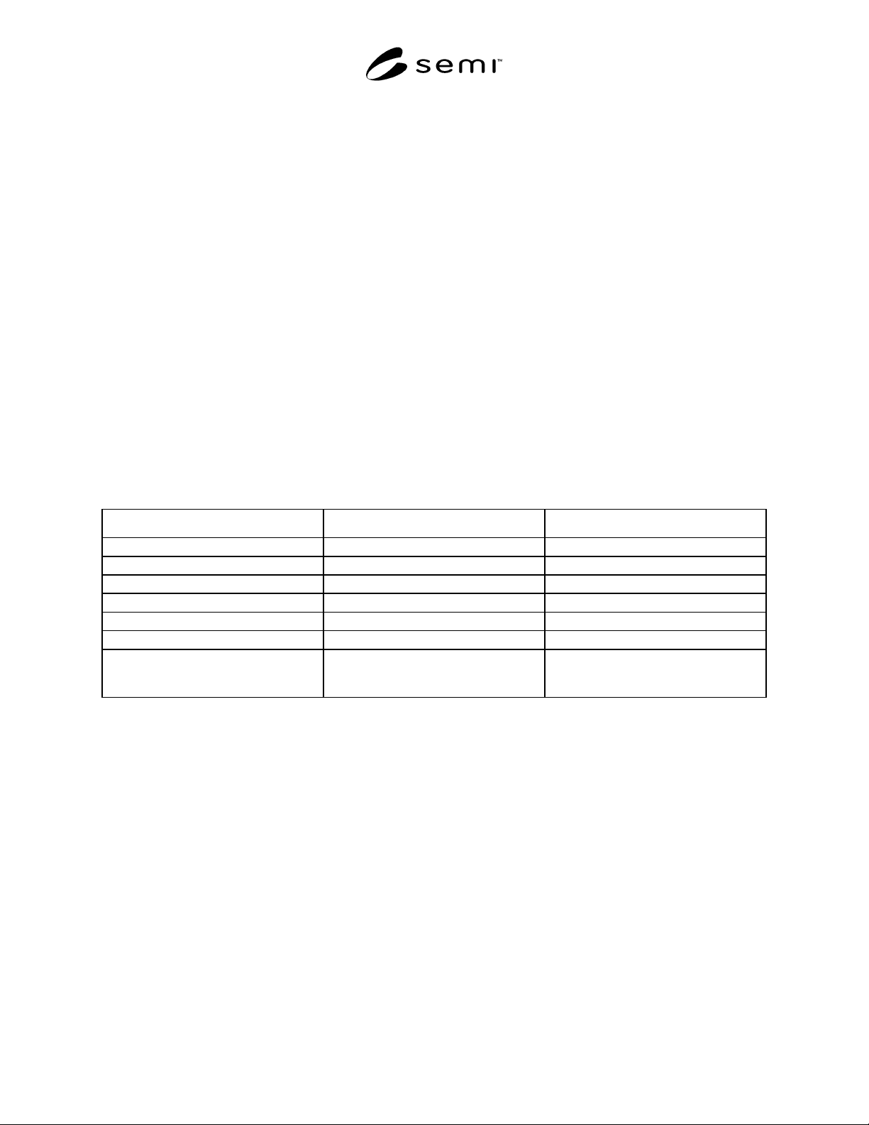
9.2.2.4 Glass Pullback (After Glass Flow) — See Table 1 and Figure 3.
Table 1 Maximum Allowable Pullback
Area of Package Package Row Spacing Package Row Spacing
0.300" (7.500 mm) and 0.400"(10.16 mm) 0.600" (15.24 mm) and larger
Side external (critical seal area) 0.010" (0.254 mm) 0.015" (0.381 mm)
Side external (non-critical seal area) 0.015" (0.381 mm) 0.015" (0.381 mm)
End external 0.020" (0.508 mm) 0.020" (0.508 mm)
Side cavity 0.010" (0.254 mm) 0.015" (0.381 mm)
End cavity 0.010" (0.254 mm) 0.015" (0.381 mm)
Maximum allowable critical seal length
reduction on any one side, as measured
between the cavity and the external side
0.015" (0.381 mm) 0.020" (0.508 mm)
NOTE 5: Regardless of the maximum criteria noted in Table 1, the critical seal length at any point shall not be reduced any more
than 30%.
9.2.2.5 Foreign Material — 0.020" (0.508 mm) maximum allowable surface dimension in the plane of the glass,
but 0.010" (0.254 mm) in the critical seal area, with no more than three sites allowed and a minimum separation of
0.030" (0.762 mm) between sites.
9.3 Die-Attach Cavity Metallization (0n Ceramic Base) — Excluding a 0.010" (0.254 mm) wide zone around the
periphery of the cavity, the following criteria shall apply:
9.3.1 Foreign Material, Including Glass Splatters — 0.005" (0.130 mm) maximum in the plane of the metallization
or greater than 0.001" (0.025 mm) in height with no more than three sites allowed and a minimum separation of
0.030" (0.763 mm) between sites.
9.3.2 Metallization Nodules — No more than three allowed. If the metallization is gold and gold-silicon eutectic die
attach is to be used, the bumps may not exceed 0.010" (0.254 mm) in the surface dimension or 0.005" (0.130 mm) in
height. If silver glass or resin bonding is to be used, the nodules shall be treated as foreign material per Section 9.3
SEMI G1-96 © SEMI 1980, 19965
9.4 Leadframe
NOTE 6: The criteria described in this section generally apply
to leadframe inspection for purchased sub-assemblies. Where
appropriate, the criteria may be used for sub-assemblies
manufactured in-house with purchased components. For
information on the criteria for leadframes purchased
separately, see SEMI G2.
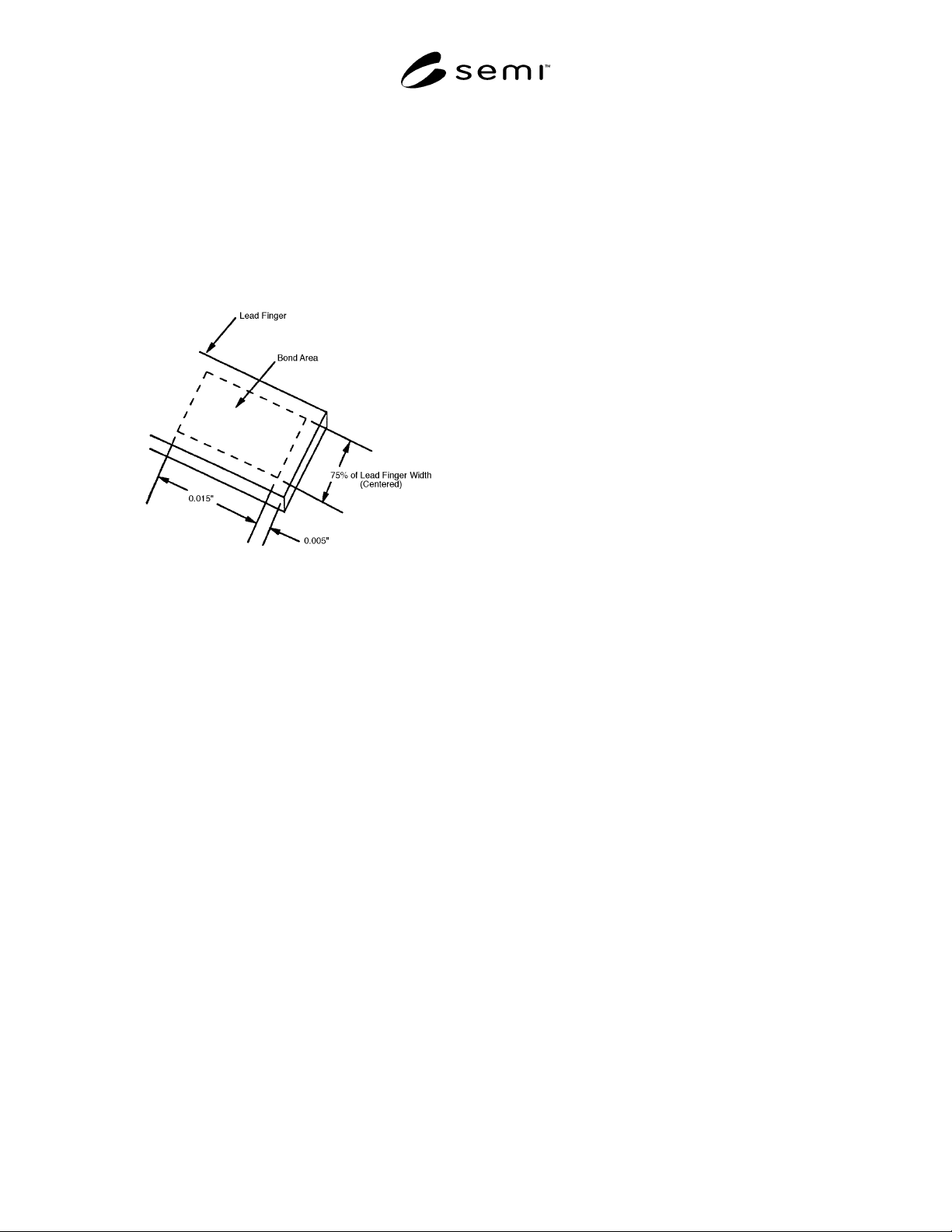
9.4.1 Lead Bond Areas — The minimum lead bond
area on the lead tip is defined in Figure 4.
Figure 4
9.4.1.1 Voids or Pits — Exposure of base metal with
any dimension greater than 0.001" (0.025 mm).
9.4.1.2 Discoloration, Blistering, or Peeling of the
Metallization
9.4.1.3 Scratches or Scrapes — Any b uild-up of
metallization or exposure of base metal.
9.4.1.4 Foreign Material, Including Glass Splatter or
Projections — No more than three sites, each with a
maximum dimension in any plane of 0.001" (0.025
mm).
9.4.1.5 Glass Wetting or Cracking — For purchased
sub-assemblies, any lead finger which is not firmly
embedded in the glass.
9.4.1.6 Glass Pullback from the Lead Tip — 0.010"
(0.254 mm) maximum.
9.4.1.7 Glass Bulge between Lead Fingers (Purchased
or In-House Sub-Assemblies) — 0.005" (0.127 mm)
height above the fingers except as agreed upon between
user and supplier for narrow pitch leads where this limit
may cause wire bond interference problems.
9.4.1.8 Lead Tip Coplanarity — 0.006" (0.15 mm)
maximum allowable difference in the position of the
top surface of the lead from highest lead to lowest lead.
9.4.1.9 Lead Tip Pitch — ± 0.002" (0.508 mm)
maximum allowable variation from true position.
9.4.2 Internal Lead Areas, Excluding Lead Bond
Areas
9.4.2.1 Burrs, Projections, and Pits — 0.002"
(0.508 mm) maximum allowable depth or height.
9.4.2.2 Foreign Material, Including Plating
Discoloration — 0.015" (0.381 mm) maximum surface
dimension or exceeding 0.002" (0.508 mm) in height.
9.4.2.3 Voids — Any exposure of base metal with a
major dimension greater than 0.002" (0.508 mm).
9.4.2.4 Blistering or Peeling of Metallization
9.4.2.5 Scratches and Scrapes — Any build-up of
metallization or exposure of base metal.
9.4.3 External Lead Areas — Unplated
NOTE 7: Non-functional areas of the leadframe, such as tie
bars, shall not be subjected to inspection unless they interfere
with handling equipment.
9.4.3.1 Scratches — Any scratch causing a loss of
more than 25% of the leadframe thickness.
9.4.3.2 Voids — Any void which violates the criteria
of Section 9.4.3.1 or causes a loss of more than 10% of
the design width of a leadframe detail.
9.4.3.3 Burrs — In excess of 0.002" (0.051 mm) in
height and 0.005" (0.127 mm) in the major dimension.
9.4.4 External Leads — Plated
NOTE 8: Non-functional areas of the leadframe, such as tie
bars, shall not be subjected to inspection unless they interfere
with handling equipment.
9.4.4.1 Scratches — Any scratch causing a loss of
more than 25% of the leadframe thickness.
9.4.4.2 Voids — Any void which violates the criteria
of Section 9.4.3.1 or causes a loss of more than 10% of
the design width of leadframe detail.
9.4.4.3 Burrs — In excess of 0.002" (0.051 mm) in
height and 0.005" (0.127 mm) in the major dimension.
9.4.4.4 Scratches and Scrapes — Any exposure of the
base metal or loss of plating integrity over more than
5% of a lead finger.
9.4.4.5 Voids — Any exposure of base metal.
9.4.4.6 Blistering or Peeling
9.4.5 Leadframe/Base/Window Assembly
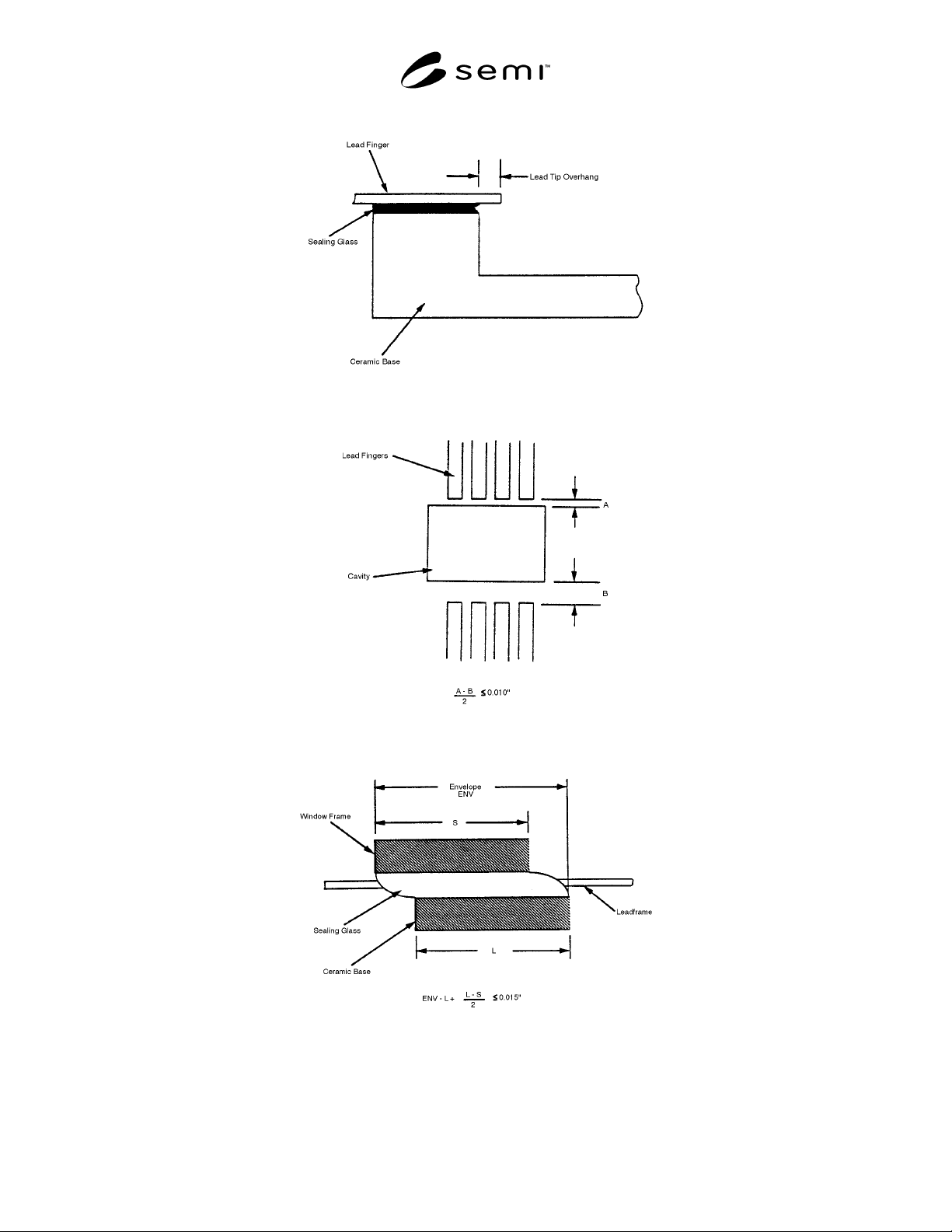
9.4.5.1 Lead Tip Overhang — 0.010" (0.254 mm)
maximum from the cavity wall (see Figure 5).
SEMI G1-96 © SEMI 1980, 1996 6
Figure 5
9.4.5.2 Lead Misalignment to Ceramic Base — 0.010" (0.254 mm) maximum (see Figure 6).
Figure 6
9.4.5.3 Window Assembly Misalignment — 0.015" (0.358 mm) maximum (see Figure 7).
Figure 7
9.4.6 Die-Attach Pad (Leadframe)
9.4.6.1 Flatness across the pad and parallelism to the base and window shall be agreed upon between user and
supplier.