semi合集-English.pdf - 第3423页
SEMI E133-0705 © SEMI 2004, 2005 4 7.2.3 Class Diagrams — UML Class Charts. 7.2.4 Name of a C lass — The text capitalizes class names. 7.2.5 Abstract and Concrete Classes — Each class is specified as Abstract or Concrete…

SEMI E133-0705 © SEMI 2004, 2005 3
5.2 Definitions
5.2.1 Advanced Process Control (APC)
1
— the manufacturing discipline for applying control strategies and/or
employing analysis and computation mechanisms to recommend optimized machine settings and detect faults and
determine their cause.
5.2.2 Analysis Engine (AE) — a process that utilizes data and possibly operational instructions to produce a
response. In the context of this standard, this term is used to encompass the characteristics common to all PCS
functional groups.
5.2.3 context — a series of attributes that uniquely identifies a manufacturing entity (e.g., wafer, lot, module, tool,
reticle) and its status in the manufacturing operation.
5.2.4 Context Matching (CM) — the process of comparing and matching the values of a set of attributes that
represent the state of a system (e.g., process, product and equipment) to a set of stored or computed values. This is
usually done so that a unique action can be specified by the context matching system.
5.2.5 Fault Classification (FC) — the technique of determining the cause of a fault once it has been detected.
5.2.6 Fault Detection (FD) — the technique of monitoring and analyzing variations in tool and/or process data to
detect anomalies. Fault detection includes both univariate and multivariate statistical analysis techniques.
5.2.7 Fault Detection and Classification (FDC) — combination of FD & FC.
5.2.8 Fault Prediction (or Prognosis) (FP) — the technique of monitoring and analyzing variations in process data
to predict anomalies.
5.2.9 Functional Group (FG) — a collection of closely related software capabilities that one would expect to be
provided as an integrated product.
5.2.10 Process Control System Job (PCSJob) — a unit of work that could be tracked and have data associated with
it. In the context of this standard a process control system job is associated with a unit of work that a PCS Analysis
Engine performs; a unique identifier such as an ID number is often utilized to track the process control system job.
5.2.11 Process Control System (PCS)
1
— a system capable of performing Process Control, which includes one or
more of R2R Control, FD, FC, FP, SPC, or any future Process Control functionality defined in this standard for a
PCS functional group.
5.2.12 Run-to-Run (R2R) Control — the technique of modifying recipe parameters or the selection of control
parameters between runs to improve processing performance. A “run” can be a batch, lot, or an individual wafer.
5.2.13 Statistical Process Control (SPC) — the technique of using statistical methods to analyze process or product
metrics to take appropriate actions to achieve and maintain a state of statistical control and continuously improve the
process capability.
6 Background
6.1 With the development of process control system applications at the factory level and inside the equipment, it is
now apparent that the lack of interface standards for these applications has inhibited widespread adoption of process
control at the factory level. Moreover, adding process control and integrated metrology capabilities inside the tool
requires the ability for the factory level applications to collaborate with tool level applications.
7 Conventions
7.1 This section defines conventions followed in this document.
7.2 Object Modeling
7.2.1 Unified Modeling Language (UML) — This specification uses UML notation for all class diagrams and for
object diagrams provided as examples. No other types of diagrams are used in this specification.
7.2.2 UML class diagrams have clearly defined meanings and are a part of this specification. Detail contained in
these diagrams is not always repeated in the text.
1 APC and PCS terms are used interchangeably in some companies. Both can be seen as the umbrella of components for process control.
SEMI E133-0705 © SEMI 2004, 2005 4
7.2.3 Class Diagrams — UML Class Charts.
7.2.4 Name of a Class — The text capitalizes class names.
7.2.5 Abstract and Concrete Classes — Each class is specified as Abstract or Concrete. Abstract classes are not
directly implemented. In this specification “implemented” means represented to the factory through the
communications interface. All classes defined as concrete may be directly implemented. This specification does
not attempt to define equipment control system implementation. In UML class diagrams, abstract class names are
shown in italics.
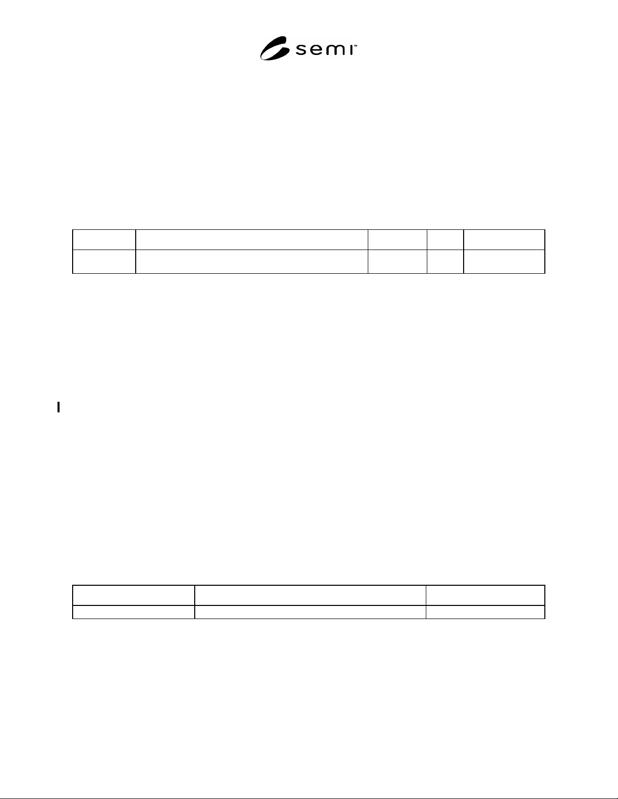
7.2.6 Class Attribute Definition — The attributes of a class are defined in table format as illustrated in the table
below. Note that the “+” sign in front of attributes in UML class diagrams indicates “public” attributes. All
attributes defined in this specification are public.
Table 1 Attribute Table Format
Attribute Name Definition Access Reqd Form
RO, RW, or
NA
Y or N See list below.
7.2.6.1 Access — Attributes may be settable (ReadWrite or RW) or not settable (ReadOnly or RO) through the
interface services. If the attribute refers to a component of a message (e.g., that is communicated to/from a PCS
analysis engine), the concept of access does not apply and “Not Applicable” (NA) is used in the Access field.
7.2.6.2 Reqd — Is this attribute required? Y — Yes, or N — No.
7.2.6.3 Form — Defines the data type of the attribute. Data types specified in the Process Control Systems
specification are described in the subsections that follow. Data types in this specification are high-level definitions
and should be mapped to the data types of a specific technology as appropriate. Extensions to the Process Control
System interface specifications are not limited to the list of data types defined in this specification. See the
definition of “Form” in the SEMI Compilation of Terms for other Form values commonly used in SEMI documents.
7.2.6.4 Constraints
7.2.6.4.1 Constraints in UML are shown with dotted lines, typically with a note attached to explain the constraint.
Constraints shown in this way tend to clutter large UML diagrams. Therefore, in this specification, constraints are
shown only on the diagrams focusing on individual classes.
7.2.7 UML Associations
7.2.7.1 The mechanism used for representing associations in UML between classes is implementation dependent.
This document is abstract in nature, and does not specify or imply any such mechanism. Any adjunct standard that
provides an implementation of this specification must include a description of the mechanism used for representing
UML associations used in this document.
7.2.8 Class Association Table — This table provides an example of the tables used to list and describe associations
between classes defined in this specification.
Table 2 Association Table Format
Association Role Name Role Definition Comments
7.2.8.1 Association Role Name — The name of the association role being defined.
7.2.8.2 Role Definition — Describes the function or purpose of the association.
7.2.8.3 Comments — Any additional comments or notes regarding the association.
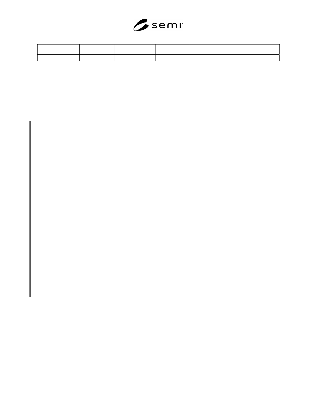
7.2.9 Method Definition — The methods (in other words, the messages that comprise the external interface to an
object) supported by a PCS functional group are defined in table format as illustrated below.
SEMI E133-0705 © SEMI 2004, 2005 5
Table 3 Method Definition Table Format
# Method Arguments Returns Requirement Behavior/Comment
Y or N
7.2.9.1 Method — Method name.
7.2.9.2 Arguments — Input parameters.
7.2.9.3 Returns — Output parameters.
7.2.9.4 Requirement — Is this method required of a compliant implementation? Y – Yes, or N – No.
7.2.9.5 Behavior/Comment — Summary description of the method’s purpose and behavior, explanation of expected
system response to this method, etc.
7.3 Data Types
7.3.1 The following data types may be used in this specification to describe the form of an attribute or other similar
high level definitions. Note that extensions to the Process Control System interface specifications are not limited to
the list of data types defined in this specification.
Any — The format may be any of the others listed in this section. Format is determined by the implementation.
Binary — A sequence of bytes that may have any value. Binary values are sometimes called “unformatted”
because their structure is not apparent.
Boolean — Takes the value of “true” or “false.”
Checksum — A checksum value calculated on a specific stream of data using a specific method of calculation.
Enumeration — A format that allows a specified list of possible values. In this document, these values are
represented as text strings, but may be implemented differently (e.g. as integers that correspond to the named
values).
Status – The Status type is a structure that contains information about whether or not an error that has occurred
in a transmission and information on the type of error. The form of the structure is given in §9.
Integer — A numeric value, Integers are always whole numbers. The form and number of bytes is left to the
implementation definition.
list of xxx — An item that can hold multiple instances of a specified type (where xxx is the data type).
Real — A numeric value that may represent any whole or fractional number. The form and number of bytes is
left to the implementation definition.
Text — A text string. Limitations on length are left to the implementation technology unless otherwise
specified in this document. Strings are recommended to be implemented as UTF-8.
Time — Representation of the date and time of the occurrence of interest. The structure and form of items of
this type is left to the implementation.
7.4 Sequence Behavior
7.4.1 Sequence behavior description is specified in the form of UML Sequence Diagrams.
7.5 State Behavior
7.5.1 State behavior description is specified in the form of UML State Charts.
8 Overview
8.1 Using the simple definition of a Functional Group given in the Terminology section, the initial set of PCS
functional groups has been identified. To identify the proper scope (and therefore the boundaries) for these groups,