semi合集-English.pdf - 第3211页
SEMI E127-0705 © SEMI 2003, 2005 12 Integrated Measure ment Module Subsystem 1...* 0...* Substrate Transfer Path 0...* Clock 0...* IMM Dat a Table Substrate Location Substrate 0...* occupied by 0...* Process Job Recipe m…

SEMI E127-0705 © SEMI 2003, 2005 11
table retention conditions (¶11.3.4).
9.2.2.1 In addition, each client may request these settings at any time and receive only their own settings in
response.
9.2.3 The first message that the IMM receives from a potential client must be the ClientConnect Service request.
This message is used to establish a client as either the Control Client or a Data Client. All other service requests
from an unestablished client shall be rejected. At any point in time, there shall be no more than one Control Client.
9.2.4 The Control Client
9.2.4.1 The Control Client is a client who intends to request services that may change the physical state of the
hardware of the IMM. Such services include those used for substrate exchange, process jobs, and any maintenance
activities. In general, this will be the controller of the integrated metrology tool or one of its major components. It
is up to the implementer whether clients connecting through a port other than the primary port can establish
themselves as the Control Client.
9.2.4.2 The Control Client shall be able to use all IMM capabilities specified in this standard. Only the Control
Client shall be permitted to use the IMM Clock Services and Process Job services, or to issue service requests that
change the state of the hardware.
9.2.4.3 Once a Control Client is established through use of the ClientConnect service, it remains established as the
Control Client until it disconnects by sending the ClientDisconnect Service request.
9.2.4.3.1 During the time that a Control Client is established, any requests to be a Control Client shall be rejected,
and any requests for services that can change the state of the hardware from other clients shall be rejected.
9.2.4.3.2 Once the Control Client has disconnected, then another client may request to establish itself as the Control
Client.
9.2.4.4 The Control Client shall be able to use all IMM capabilities specified in this standard. Only the Control
Client shall be permitted to use the IMM Clock Services and Process Job services, or to issue service requests that
change the state of the hardware.
9.2.5 Data Clients
9.2.5.1 The Data Client is a client who intends to request services for information only and not for any services that
may change the physical state of the hardware of the IMM. Each Data Client may request information at any time.
9.2.5.2 The use of the Data Client is optional for the end-user.
9.3 Bandwidth and Performance
9.3.1 The IMM is responsible for managing its own bandwidth and performance. This standard allows for delays in
message transmission in a multi-client environment in order to protect the integrity of the IMM measurement and
data conversion abilities.
10 Integrated Measurement Module Object Model
10.1 Description
10.1.1 The Integrated Measurement Module (IMM) conforms to the architectural specification of the
EquipmentModule object as defined in SEMI E120 (CEM).
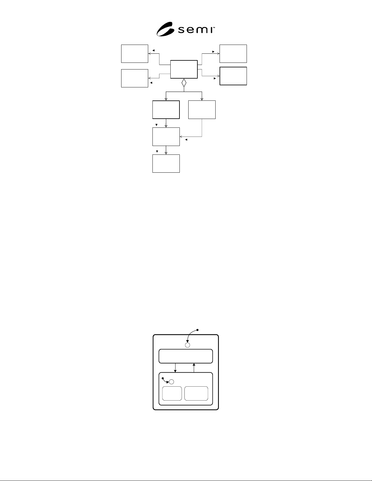
10.1.2 Figure 1 shows an object model for the Integrated Measurement Module and its significant components.
SEMI E127-0705 © SEMI 2003, 2005 12
Integrated
Measurement
Module
Subsystem
1...*
0...*
Substrate
Transfer Path
0...*
Clock
0...*
IMM Data
Table
Substrate
Location
Substrate
0...*
occupied by
0...*
Process
Job
Recipe
manages
uses
contains
0...*
0...*
1
provides
manages
provides
Figure 1
IMM Object Model
10.1.3 The IMM has exactly one internal clock. It must have one or more measurement subsystems capable of
holding one or more substrates in a substrate location. It may have additional components, such as OCR
subsystems. Pattern recognition and analysis subsystem typically do not hold any material. The Clock shall be
provided as an OBEM-compliant clock object. Subsystems shown in Figure 1 are not required to be visible as
objects externally.
11 The Integrated Measurement Module Object
11.1 Relationship of IMM Object And Physical Module
11.1.1 The IMM object represents the IMM module and all of its internal components to its client. It is responsible
for ensuring proper behavior in all cases. In this document, the IMM object is considered synonymous with the
IMM module. The IMM provides all services to the client other than those specifically directed to the STPO,
including those specified by other SEMI standards.
11.2 IMM Service State Model
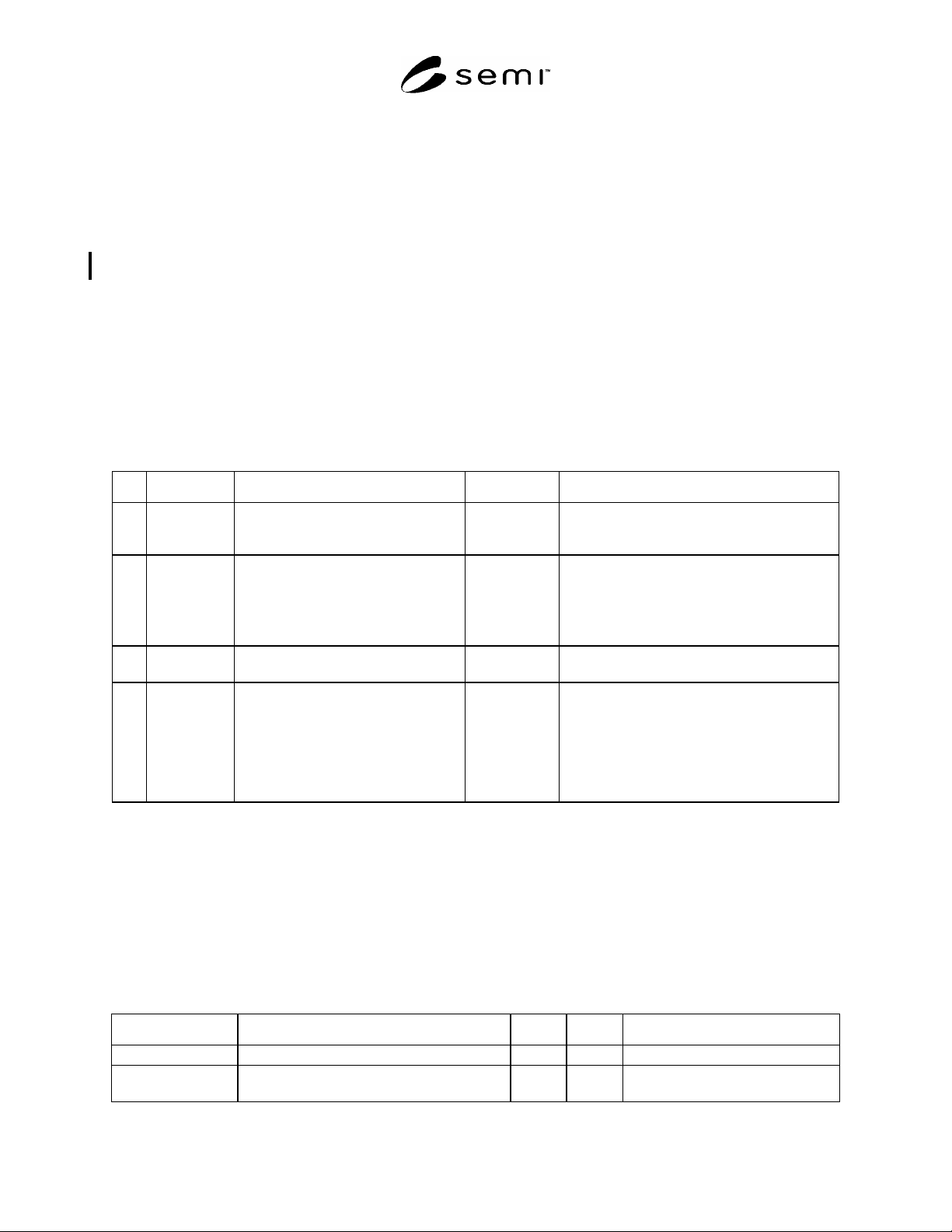
11.2.1 The IMM is either in a state where it can be used for normal measuring purposes or it is not. This is
reflected in the Service State Model as shown in Figure 2.
SERVICE
C
1
IN SERVICE
3
EXTERNAL
SELECT
INTERNAL
SELECT
2
C
4
NOT IN
SERVICE
Figure 2
IMM Service State Model
SEMI E127-0705 © SEMI 2003, 2005 13
11.2.2 The IMM Service state model shows its availability for process jobs. It has two states, IN SERVICE and
NOT IN SERVICE. The IMM shall only accept or initiate process jobs while in the IN SERVICE state.
11.2.3 State Definitions
11.2.3.1 IN SERVICE — In this state, the IMM is capable of performing all its normal activities for measurement. It
is able to accept and execute a process job or may be currently executing a process job. No faults or exceptions exist
that would interfere with its capability of loading, measuring, and unloading a substrate.
11.2.3.2 NOT IN SERVICE — In this state, the IMM shall not accept new process jobs or initiate execution of
existing process jobs. It may be able to perform special services required for maintenance and diagnostics, including
calibration and associated loading/unloading activities. Either the external Control Client or the IMM may put it in
an NOT IN SERVICE state. Once put into NOT IN SERVICE, only the one who put it NOT IN SERVICE may
change the state back to IN SERVICE. This is reflected in the two substates, EXTERNAL SELECT and
INTERNAL SELECT.
11.2.3.3 EXTERNAL SELECT — The Control Client has placed the IMM out of service.
11.2.3.4 INTERNAL SELECT — The IMM has placed itself out of service due to a fault condition.
11.2.4 Service State Model Transitions — Transitions are defined for the Service State Model in Table 1.
Table 1 Service State Model Transitions
# Previous State Trigger New State Comment
1 (no state) IMM initialization. IN SERVICE
or NOT IN
SERVICE
Initial state is determined first by existence of
exceptions or alam conditions. If none, then
initial state shall be the last known state.
2 IN SERVICE The IMM detects one of the conditions
for NOT IN SERVICE
OR
The IMM client has issued a
ChangeService request.
NOT IN
SERVICE
Transitions 2 and 4 are combined for reporting
purposes.
3 NOT IN
SERVICE
The IMM or communications partner
has returned the IMM to IN SERVICE.
IN SERVICE
4 System
initialization
or
IN SERVICE
Entry into NOT IN SERVICE:
4-1 Following system initialization,
4-2 IMM initiated state change, and
4-3 Client requested state change.
EXTERNAL
SELECT
(trigger 4-3)
or INTERNAL
SELECT
(triggers 4-1 or
4-2)
Transitions 2 and 4 are combined for reporting
purposes.
11.2.5 The Control Client may request a state change through a Service request at any time.
11.2.6 A transition to OUT OF SERVICE shall not interrupt any process job currently executing. It is
recommended that all transitions to OUT OF SERVICE be delayed until such process jobs have completed, either
normally or abnormally. This avoids confusion or an unintended internally-generated abort of process jobs. Process
jobs must be aborted separately and deliberately when necessary.
11.3 Object Attributes
11.3.1 Table 2 defines the attributes of the IMM Object as shown in Figure 3.
Table 2 IMM Object Attribute Definitions
Attribute Name Definition Access Reqd Form
ObjType Defines object type. RO Y Text = “EquipmentModule”
ObjID Identifier of specific module. RO Y Conforms to requirement of ObjID
(SEMI E39).