semi合集-English.pdf - 第3819页
10 Related Documents 29 CFR 1910.1000 Code of Federal Regulatio ns, Title 29, Superinten dent of Documents, U.S. Governm ent Printing O ffice, Washingt on, D.C. 204 02. ACGIH American Confe rence of Governmental Indu…
injection line should be capped, except when performing an
injection test.
7.3.5 Perform several tests with differing directions of
release relative to any opening or penetration in the
enclosure. The location and direction of the release
shall effectively simulate an actual gas release or
tubing/fitting failure within the enclosure. A worst case
failure can be simulated by locating the tracer injection
point at the potential leak location closest to a
penetration or opening within the enclosure with the
direction of tracer injection pointed directly at the
opening or penetration.
7.3.6 After initiation of tracer injection, collect grab air
samples from the area surrounding the enclosure at
predetermined times and locations. These samples
should be analyzed immediately after collection. If this
is not possible, they should be sealed. Label the
samples as to time and location. Samples may be taken
with: a) Containers that are non-absorbent, inert, and
that have low permeability (such as polyvinyl fluoride
film or polyester film sample bags or polyethylene,
polypropylene, nylon, or glass bottles) or b) disposable
syringes. Disposable syringes can be used to inject
samples into the gas chromatograph directly.
7.3.7 Record: a) the actual (measured) tracer gas
release rate, b) the actual SF
6
concentration in the tracer
gas being used, and c) the actual release time during a
test.
7.3.8 Collect air samples as described in Section 7.3.6,
and analyze them for the presence or absence of tracer
gas using a gas chromatograph. The measurement of a
non-zero tracer concentration in the area surrounding an
enclosure indicates incomplete containment of
contaminants within the enclosure.
7.3.9 Analyze samples according to ASTM E 260 and
ASTM E 697 in conjunction with the chromatograph
manufacturer's operating procedures. Samples may be
analyzed immediately after a test, or they may be stored
for future analysis. Experience has shown no
degradation of concentration in polypropylene syringes
when stored for several months as long as the needle or
syringe is plugged. Polypropylene syringes should be
discarded after one use to eliminate the possibility of
cross contamination of samples.
8 Calculations and Interpretation of Results
8.1 The maximum concentration of SF
6
measured in a
sample collected outside the enclosure is used to
calculate the Equivalent Release Concentration (ERC)
by the following formula:
ERC =
Conc. o
f
process gas
Measure
d
SF
6
Conc.
Tracer Injection gas conc.
8.1.1 The above formula assumes the process gas
tubing that fails is the same diameter as the tracer gas
injection tubing. Appendix 3 contains a general
equation that can be used when this is not the case.
8.2 Compare the Equivalent Release Concentration to
the hazardous process gas TLV or PEL, whichever is
lower. If the ERC is above the prescribed limits, the
enclosure is not considered to be acceptable; if the ERC
is less than or equal to the prescribed limit, the
enclosure is considered acceptable. SEMI S2
recommends appropriate control limits for an enclosure.
9 Reporting Results
9.1 Present all results in tabular form in a manner
which unambiguously notes those enclosure(s) that do
not satisfy the criteria of SEMI S2. The exhaust
operating conditions during each test must be provided
along with each measured ERC value.
9.2 Describe tracer gas injection points within
individual enclosures to detail location and proximity to
openings, penetrations, exhaust grillwork, access
panels, and other potential leakage sites, such that worst
case leak conditions have been simulated.
9.3 Describe the unit being tested by manufacturer,
model number, and serial number to provide
identification of the unit being tested.
9.4 Tabulate and record the name, supply
concentration, maximum flow rate, and TLV or PEL for
each hazardous gas or vapor used within each enclosure
being tested.
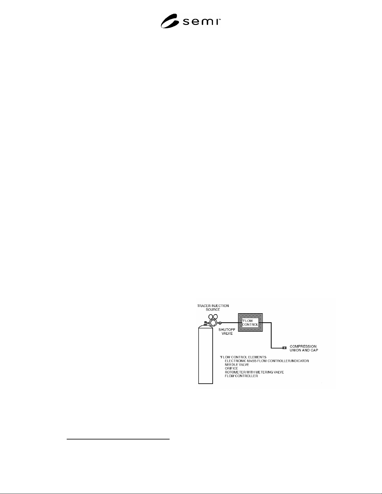
Figure 2
Schematic Drawing of Injection Manifold
SEMI F15-93 © SEMI 1993, 2004 3

10 Related Documents
29 CFR 1910.1000 Code of Federal Regulations,
Title 29, Superintendent of Documents, U.S.
Government Printing Office, Washington, D.C. 20402.
ACGIH American Conference of Governmental
Industrial Hygienists, 6500 Glenway, Building D-7,
Cincinnati, OH 45211-4438, (513)661-7881. Industrial
Ventilation - A Manual for Recommended Practice,
20th ed. ISBN: 0-936712-65-1.
American Industrial Hygiene Association 345 White
Pond Drive, Akron, OH 44320, (216)873-2442.
Workplace Environmental Exposure Level Guides.
ASTM American Society for Testing and Materials,
1916 Race Street, Philadelphia, PA 19103. ASTM
Standard E741-83 (Determining Air Leakage Rate by
Tracer Dilution).
BOCA Building Officials and Code Administrators
International Inc., 4051 West Flossmoor Road, Country
Club Hills, IL 60478-5795, (708)799-2300. National
Fire Prevention Code.
Grot, R.A. and P.L. Lagus “Applications of Tracer
Gas Analysis to Industrial Hygiene Investigations,”
Industrial Hygiene News, May 1991.
Orcutt, J.R. “Characterization of Hazardous Gas
Releases by Tracer Gas Simulation,” Hazardous
Assessment and Control Technology in Semiconductor
Manufacturing, ACGIH, Cincinnati, OH, 1988.
SBCCI Southern Building Code Congress
International, 900 Montclair Road, Birmingham, AL
35213-1206, (205)591-1853. Standard Fire Prevention
Code.
Tubby, R.L. “Tracer Gas Testing of Secondary
Exhaust Systems on Hazardous Gas Enclosures,” SSA
Journal, Vol. 5, June 1991.
UFC Uniform Fire Code. International Conference
of Building Officials and Western Fire Chiefs
Association, 5360 South Workman Mill Road, Whittier,
CA 90601. 1988 Edition, ISSN 0896-9736.
SEMI F15-93 © SEMI 1993, 2004 4

APPENDIX 1
EQUILIBRIUM TIME FOR TRACER INJECTION
NOTICE: The material in this appendix is an official part of SEMI F15 and was approved by full letter ballot procedures.
A1-1
A1-1.1 If a tracer gas is injected at a constant rate into
an enclosure that possesses a constant ventilation rate,
the concentration as a function of time is given as
C(t) = (F/q) [1 - exp{-(q/V)t}] (A1 -1)
where C t Concentration within the enclosure
F Injection rate of tracer gas
q Ventilation rate of enclosure
V Volume of enclosure
t Elapsed time since initiating injection
A1-1.2 Note that the term (q/V) contained in the
exponential is the air change rate. In order for the
concentration C(t) to be constant, the exponential term
must be approximately zero. This is generally taken as
the time when the exponential term is equal to e
-3
. The
time at which this occurs can be found by setting (q/V)t
= 3 and solving for t. Thus,
(q/V)t = 3 A1- 2
from which it follows that the equilibrium time is given
as,
t 3/(q/V) (A1- 3)
t = 3(V/q) (A1-4)
SEMI F15-93 © SEMI 1993, 2004 5