semi合集-English.pdf - 第642页
SEMI E84-0305 © SEMI 1999, 2005 40 A1-3.2.2 Recovery Sequences A1-3.2.2.1 Should an error occ ur during transfer ope rations (refer to Tables 1 and 2 ), the recovery s hould begin by returning the carrier to the stocker …
SEMI E84-0305 © SEMI 1999, 2005 39
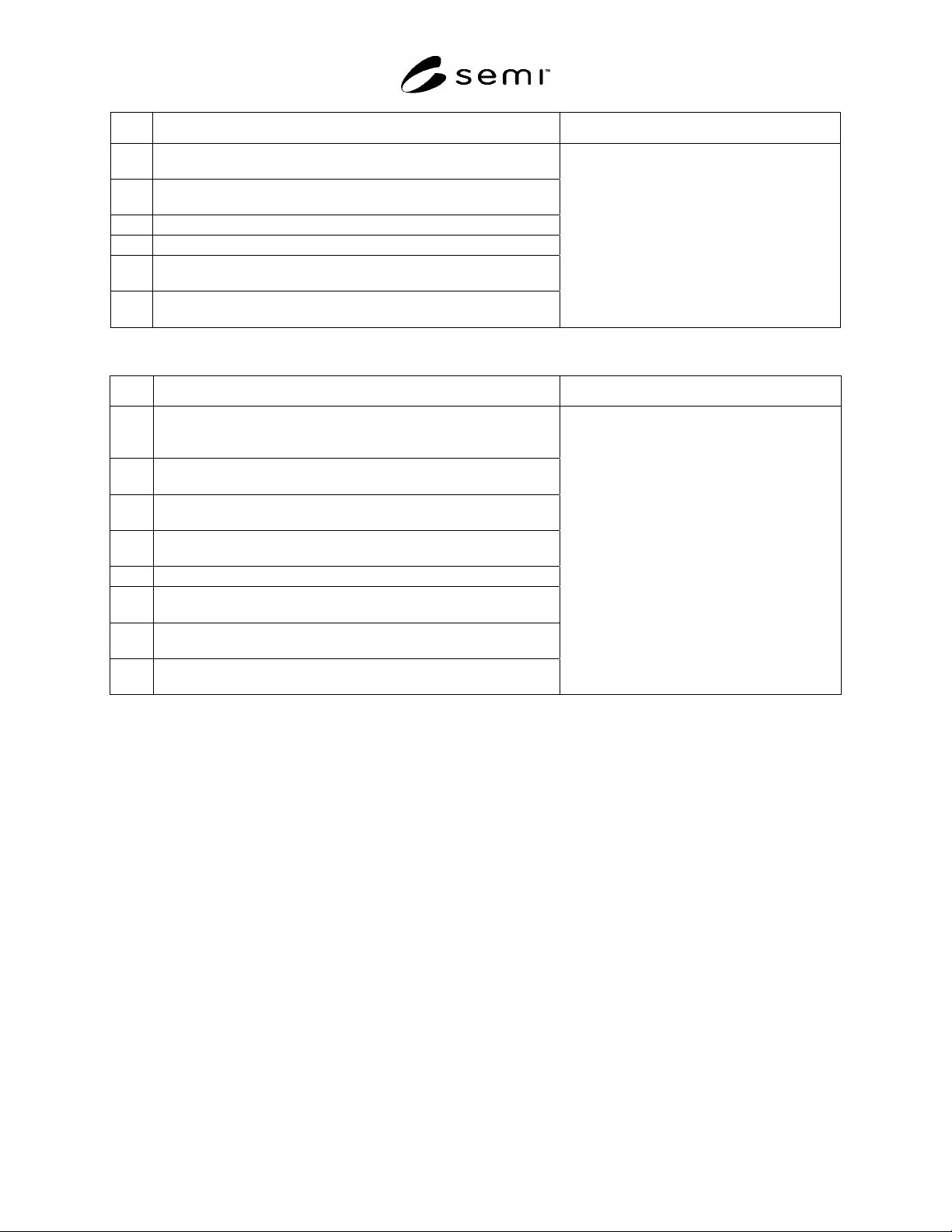
No. Error Description OHS Reaction
3
Anytime during the load operation the load presence status on the
loader does not match the actual conditions of the current operation.
4
The READY signal does not go ON within the specified amount of
time after the TR_REQ signal is output.
5 The READY signal goes OFF during the load operation.
6 The L_REQ signal remains ON after the load operation is completed.
7
The READY signal does not go OFF within the specified amount of
time after the COMPT signal is output.
8
Anytime during the load operation the optical transmission beam is
interrupted.
Table A1-2 Unload Operation Errors
No. Error Description OHS Reaction
1
The OHS moves to the stocker (for an unload operation) and outputs
the VALID signal, but the U_REQ signal remains OFF for a specified
amount of time.
2
Anytime during the transfer an unload operation failure or stop
positioning failure is detected.
3
Anytime during the unload operation the load presence status on the
loader does not match the actual conditions of the current operation.
4
The READY signal does not go ON within the specified amount of
time after the TR_REQ signal is output.
5 The READY signal goes OFF during the unload operation.
6
The U_REQ signal remains ON after the unload operation is
completed.
7
The READY signal does not go OFF within the specified amount of
time after the COMPT signal is output.
8
Anytime during the unload operation the optical transmission beam is
interrupted.
The unload operation sequence is stopped and
an error is displayed.
A1-3.2.1 Example of the Signal Status When an Error is Generated During Transfer Operations
A1-3.2.1.1 OHS Side Error Generation
A1-3.2.1.1.1 OHS Side Signals — When an error is generated, the BUSY signal must stay ON. This is to prevent
secondary accidents due to the other device operating on its own.
A1-3.2.1.1.2 Stocker Side Signals — When an error is generated, each signal (except for the READY signal) should
remain in the status it was in at the time of the error. The READY signal should go OFF.
A1-3.2.1.2
Stocker Side Error Generation
A1-3.2.1.2.1 Stocker Side Signals — When an error is generated, each signal should remain in the status it was in at
the time of the error.
The READY signal should be OFF.
The ES signal should be OFF.
HO_AVBL should be OFF.
A1-3.2.1.3 OHS Side Signals — When an error is generated, only the BUSY signal should go ON. All remaining
signals should go OFF.
SEMI E84-0305 © SEMI 1999, 2005 40
A1-3.2.2 Recovery Sequences
A1-3.2.2.1 Should an error occur during transfer operations (refer to Tables 1 and 2), the recovery should begin by
returning the carrier to the stocker or OHS. Then, the error should be recovered. The four recovery scenarios are:
1. Load operation, carrier is returned to the stocker.
2. Load operation, carrier is returned to the OHS.
3. Unload operation, carrier is returned to the stocker.
4. Unload operation, carrier is returned to the OHS.
A1-3.2.3 Recovery Method
A1-3.2.3.1 OHS Side
In the case of sequence 2 (above), the load/unload sequence should be started over from the beginning.
In the case of sequence 3 (above), the corresponding transfer operation should be canceled.
In the case of sequences 1 and 4 (above) the corresponding transfer operation should be considered completed.
A1-3.2.3.2 Stocker Side
In the case of sequences 1 and 4 (above) the corresponding transfer operation should be considered completed.
In the case of sequences 2 and 3 (above), the load/unload sequence should be started over from the beginning.
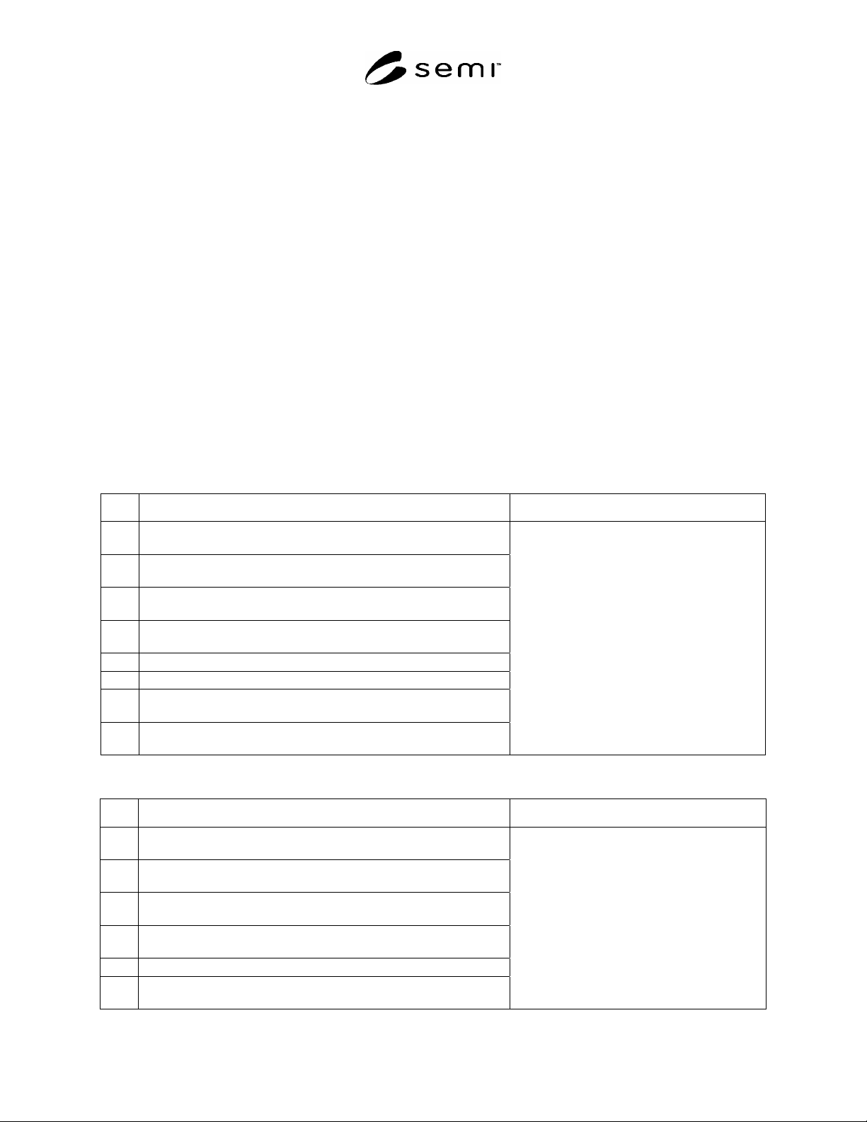
Table A1-3 Load Operation Errors
No. Error Description Stocker Reaction
1
The L_REQ does not go OFF in the allotted amount of time during
an unload transaction.
2
Anytime during the transfer a load operation failure or stop
positioning failure is detected.
3
Anytime during the load operation the load presence status on the
loader doesn't match the actual conditions of the current operation.
4
The READY signal does not go ON within the specified amount of
time after the TR_REQ signal is output.
5 The READY signal goes OFF during the load operation.
6 The L_REQ signal remains ON after the load operation is completed.
7
The READY signal does not go OFF within the specified amount of
time after the COMPT signal is output.
8
Anytime during the load operation the optical transmission beam is
interrupted.
The load operation sequence is stopped and an
error is displayed.
Table A1-4 Unload Operation Errors
No. Error Description Stocker Reaction
1
The stocker (for an unload operation) outputs the VALID signal, but
the U_REQ signal remains OFF for a specified amount of time.
2
Anytime during the transfer an unload operation failure or stop
positioning failure is detected.
3
Anytime during the unload operation the load presence status on the
loader doesn't match the actual conditions of the current operation.
4
The READY signal does not go ON within the specified amount of
time after the TR_REQ signal is output.
5 The READY signal goes OFF during the unload operation.
6
The U_REQ signal remains ON after the unload operation is
completed.
The unload operation sequence is stopped and
an error is displayed.

SEMI E84-0305 © SEMI 1999, 2005 41
No. Error Description Stocker Reaction
7
The READY signal does not go OFF within the specified amount of
time after the COMPT signal is output.
8
Anytime during the unload operation the optical transmission beam
is interrupted.
A1-3.3 Stocker (Active Type) Error Examples
A1-3.3.1 Example of the Signal Status When an Error is Generated During Transfer Operations
A1-3.3.1.1 Stocker Side Error Generation
A1-3.3.1.1.1 Stocker Side Signals — When an error is generated, the BUSY signal must stay ON. This is to
prevent secondary accidents due to the other device operating on its own.
A1-3.3.1.1.2 OHS Side Signals — When an error is generated, each signal (except for the READY signal) should
remain in the status it was in at the time of the error. The READY signal should go OFF.
A1-3.3.1.2
OHS Side Error Generation
A1-3.3.1.2.1 OHS Side Signals — When an error is generated, each signal should remain in the status it was in at
the time of the error.
The READY signal should be OFF.
The ES signal should be OFF.
HO_AVBL should be OFF.
A1-3.3.1.2.2 Stocker Side Signals — When an error is generated, only the BUSY signal should go ON. All
remaining signals should go OFF.
A1-3.3.2 Recovery Sequences
A1-3.3.2.1 Should an error occur during transfer operations (refer to Tables 3 and 4), the recovery should begin by
returning the carrier to the stocker or OHS. Then, the error should be recovered. The four recovery scenarios are:
1. Load operation, carrier is returned to the OHS.
2. Load operation, carrier is returned to the stocker.
3. Unload operation, carrier is returned to the OHS.
4. Unload operation, carrier is returned to the stocker.
A1-3.3.3 Recovery Method
A1-3.3.3.1 Stocker Side
In the case of sequences 2 and 3 (above), the load/unload sequence should be started over from the beginning.
In the case of sequences 1 and 4 (above) the corresponding transfer operation should be considered completed.
A1-3.3.3.2 OHS Side
In the case of sequences 1 and 4 (above) the corresponding transfer operation should be considered completed.
In the case of sequences 2 and 3 (above), the load/unload sequence should be started over from the beginning.
A1-3.4 If the stocker is the active side of the interbay AMHS (i.e., OHS and stockers) it is conceivable that the
loader will interfere with the OHS passing by the stocker in failure scenarios. As a result of this possibility, it is
necessary for interbay AMHS equipment makers to establish an OHS “PASS OK” signal separate from the SEMI
E84 interlock. However, this note has no direct bearing on the contents of SEMI E84. Therefore, readers of SEMI
E84 should only treat this as a reference item.
Pass Interlock