semi合集-English.pdf - 第4409页
SEMI F97-0305 © SEMI 2005 19 11.2.2.3 Post Conditions: Post condition 1..n: Th e FPU shall reflect the new value of the variable set by the Set Data. 11.2.2.4 It is recommended that all parameters supported by Set Data…

SEMI F97-0305 © SEMI 2005 18
10 Mapping to Various Communication Solutions
10.1 This standard does not make any assumptions about how the mapping to the communications protocols is
made.
11 Test Methods and Compliance
11.1 Overall Precondition — The precondition for testing the FPU (and the FMCS) is the agreement between
supplier and purchaser on a common set of issues which include:
communication hardware and protocols to be used for the integration between FMCS and FPU,
data formats and semantics to be transferred between FMCS and FPU,
FMCS and FPU are initialized, the FPU reflects already a valid run state,
FMCS shall be able to issue a Get Status, and
FMCS shall be able to visualize the results of the tests.
11.1.1 See ordering information (§7) and Related Information 2 (§R2).
11.2 Tests
11.2.1 Get Status Test
11.2.1.1 Preconditions:
FMCS and FPU are connected.
FMCS is ready to issue a Get Status.
11.2.1.2 Test Operations:
Operation 1: The FMCS shall issue a Get Status against the FPU.
Operation 2: The FMCS shall issue a Get Status against the FPU. The FPU shall alternate the Watchdog-
Toggle.
Operation 3..n: The status of all status variables at the FPU is forced at least to change once; after each status
change a new Get Status request shall be issued against the FPU.
11.2.1.3 Post Conditions:
Post condition 1: The FPU shall respond with all requested parameters in the Status Response. The result shall
be visualized by the FMCS and show the returned values of all supported status variables.
Post condition 2: The FMCS shall visualize that the FPU is still alive or not alternating the Watchdog-Toggle
within the specified time window.
Post condition 3..n: The FPU shall respond with the changed status variable values. In each case the result of
all supported status variables shall be visualized by the FMCS.
11.2.1.4 All status values of the Run-Mode shall be used at the FPU to show that state changes are correctly
maintained and transmitted to the FMCS.
11.2.2 Set Data Test (if supported by FPU)
11.2.2.1
Preconditions:
FMCS and FPU are connected.
FMCS is ready to issue a Set Data.
FMCS shall be able to enter the data to be transmitted by Set Data.
11.2.2.2 Test Operations:
Operation 1..n: The FMCS shall issue a Set Data against the FPU.

SEMI F97-0305 © SEMI 2005 19
11.2.2.3 Post Conditions:
Post condition 1..n: The FPU shall reflect the new value of the variable set by the Set Data.
11.2.2.4 It is recommended that all parameters supported by Set Data are tested.
11.2.3 Get Data Test (if supported by FPU)
11.2.3.1 Preconditions:
FMCS and FPU are connected.
FMCS is ready to issue a Get Data.
11.2.3.2 Test Operations:
Operation 1..n: A test person shall set the variable at the FPU to a particular value. The FMCS shall issue a Get
Data against the FPU.
11.2.3.3 Post Conditions:
Post condition 1..n: The FMCS shall visualize the new value of the variable.
11.2.3.4 It is recommended that all parameters supported by Get Data are tested.
11.3 Compliance
11.3.1 Table 15 provides a checklist for compliance with this standard.
Table 15 Compliance Checklist
Section Implemented Compliant
Fundamental Requirements
Watchdog-Toggle 9.4.2 Yes No Yes No
OP-Mode 9.4.3 Yes No Yes No
Run-Mode 9.4.5 Yes No Yes No
Error-Mode 9.4.8 Yes No Yes No
Get Status Operation 9.5.2 Yes No Yes No
Optional Capabilities
Control-Mode 9.4.4 Yes No Yes No
Alarm-Mode 9.4.6 Yes No Yes No
Warning-Mode 9.4.7 Yes No Yes No
Maintenance-Mode 9.4.9 Yes No Yes No
Simulation Mode 9.4.10 Yes No Yes No
Lock-Mode 9.4.5.2 Yes No Yes No
Set Data Operation 9.5.3 Yes No Yes No
Get Data Operation 9.5.4 Yes No Yes No
SEMI F97-0305 © SEMI 2005 20
RELATED INFORMATION 1
APPLICATION EXAMPLES
NOTICE: This related information is not an official part of SEMI F97 and was derived from work of the originating
task force. This related information was approved for publication by full letter ballot on November 10, 2004.
R1-1 Application Examples
R1-1.1 In order to help with understanding of FPU states specified in this standard, this Related Information
provides examples of their use. Examples of simple and more complex FPUs are given. The status of the FPU
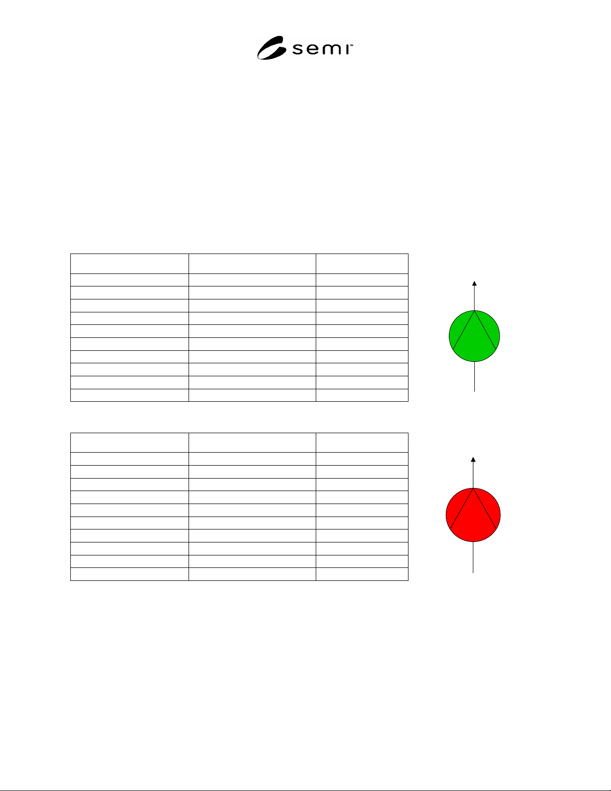
retrieved by the FMCS is depicted in a table. In addition, a picture is given that might visualize the FPU status by
the FMCS.
R1-2 Simple FPU – Pump
Table R1-1 Status Response of a Pump in Operation
Status Field Name Meaning Value FMCS- Visualization
Watchdog-Toggle Toggle value (not supported) 0
OP-Mode Automatic 1
Control-Mode Local 0
Run-Mode Run 3
Alarm-Mode No_Alarm 0
Warning-Mode No_Warning 0
Error-Mode No_Error 0
Maintenance-Mode No_Maintenance 0
Simulation-Mode No_Simulation 0
Lock-Mode Not_Locked 0
Table R1-2 Status Response of a Pump That is Not Operating Because of an Alarm, e.g. Motor-Overheat
Status Field Name Meaning Value FMCS- Visualization
Watchdog-Toggle Toggle value (not supported) 0
OP-Mode Automatic 1
Control-Mode Local 0
Run-Mode Down (unscheduled) 0
Alarm-Mode Alarm 1
Warning-Mode No_Warning 0
Error-Mode No_Error 0
Maintenance-Mode No_Maintenance 0
Simulation-Mode No_Simulation 0
Lock Not_Locked 0