semi合集-English.pdf - 第5773页
SEMI P22-0699 © SEMI 1993 , 1999 3 Figure 3 Figure 4 Edge Extensio n Edge Intrusio n S1 1/2 1/2 S1 1/2 1/2 Figure 5 Figure 6 Corner Extension Corner Intrusion Figure 7 Figure 8 Opaque Bri dge Clear Bridge
SEMI P22-0699 © SEMI 1993, 1999 2
growth, electrostatic damage, organic material deposit,
Phase shift defect).
6 Definition of Size for Photomask Defects
6.1 The tools and conditions used to measure defect
size should be clearly specified.
6.2 Pattern Defects
6.2.1 Shape Defects
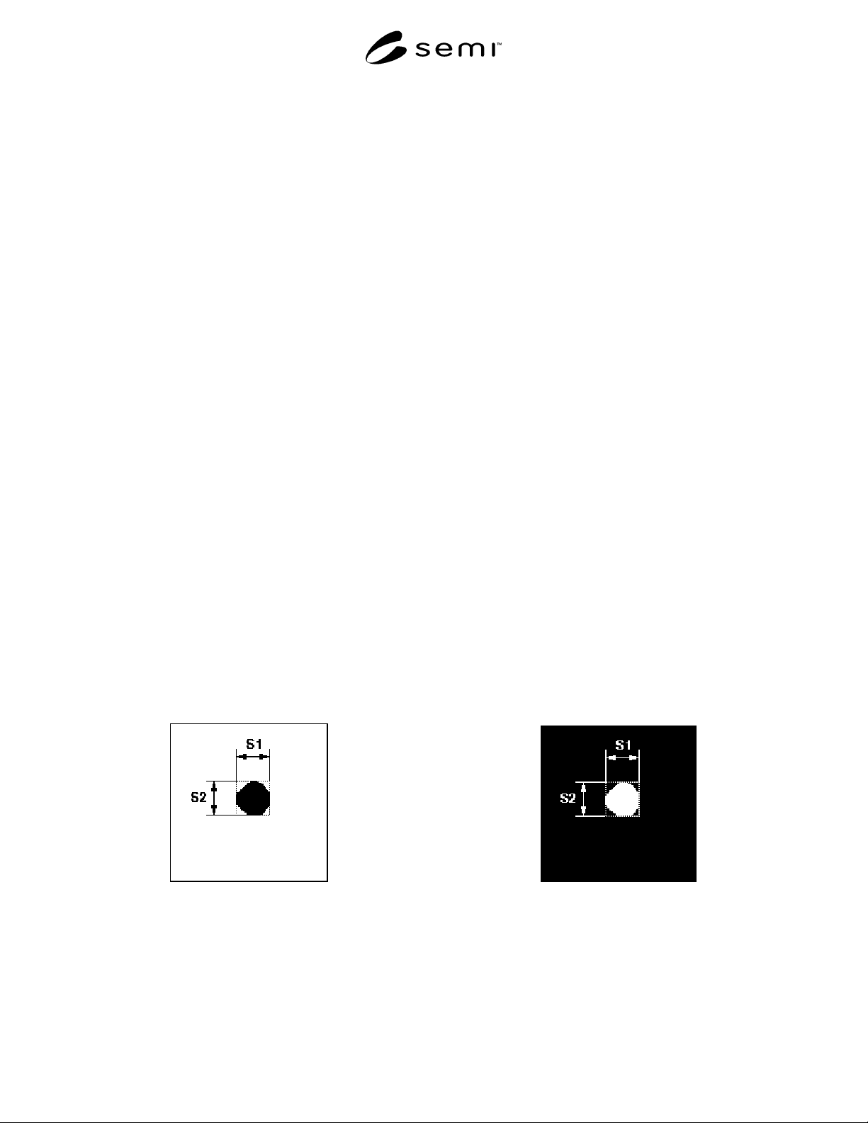
6.2.1.1 Isolated Defect — defect size is expressed as
two dimensions (S1 and S2) of the smallest rectangle
that encloses the defect. (See Figures 1, 2, 23)
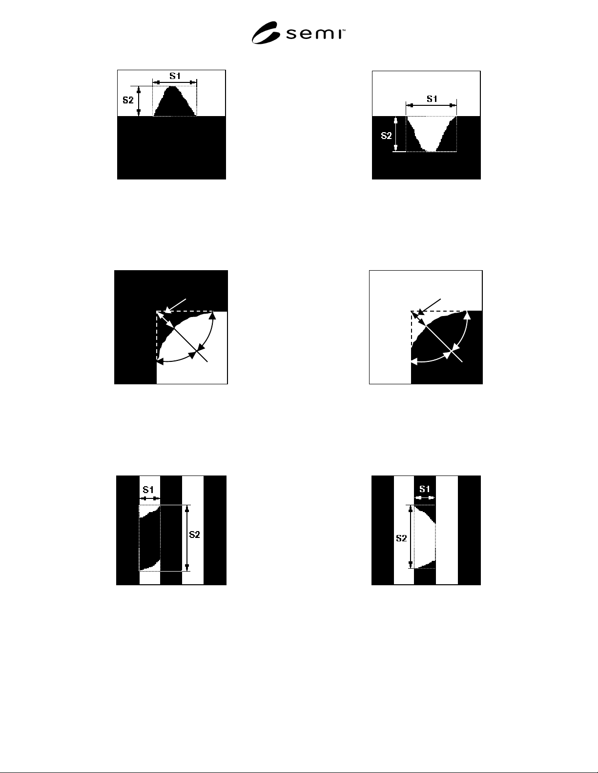
6.2.1.2 Edge Defect — defect size is expressed as two
dimensions (S1 and S2) of the smallest rectangle that
encloses the defect. (See Figures 3, 4, 24)
6.2.1.3 Corner Defect — defect size is expressed as
the distance (S1) between the intersection point, formed
by the bisection of the corner angle and the pattern, and
the point designed. (See Figures 5, 6)
6.2.1.4 Bridge — defect size is expressed as two
dimensions (S1 and S2) of the smallest rectangle that
encloses the defect. (See Figures 7, 8, 26)
6.2.2 Size Defects
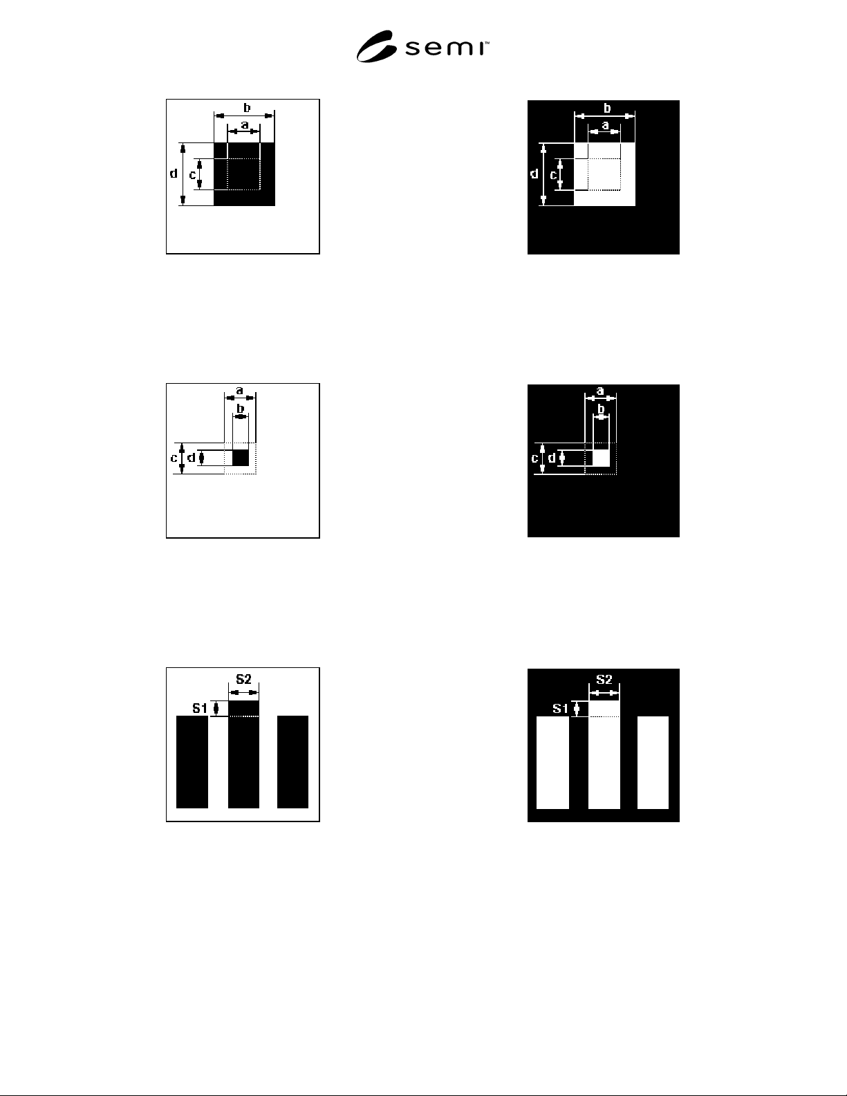
6.2.2.1 Oversize and Undersize — defect size is
expressed as two dimensions (S1 and S2) representing
the absolute value of the deviation from the intended
design pattern.
S1 = | b - a |
S2 = | d - c |
“a” and “c” are intended value; “b” and “d” are actual
measured value. (See Figures 9, 10, 11, 12)
6.2.2.2 Elongation and Truncation — defect size is
expressed as two dimensions (S1 and S2) of the
smallest rectangle that encloses the deviation from the
intended design pattern. (See Figures 13, 14, 15, 16)
6.2.3 Misplacement Defect — defect size is expressed
as the absolute value of X and Y displacement from its
intended position. (See Figures 17, 18, 25)
6.2.4 Transmission Defect — transmission defects are
evaluated by their transmissivity in addition to the size.
The wavelength used for measurement should be
clearly specified, as well as the transmissivity error
(Te). Defect dimensions should be consistent with
other definitions. (See Figures 19, 20)
Te = Td - Ti
where
Td = transmissivity of defect
Ti = intended transmissivity of design
6.2.5 Missing Pattern Defect — defect size is
expressed as two dimensions (S1 and S2) of the
smallest rectangle that encloses the intended design
pattern. (See Figures 21, 22)
6.3 Randomly Shaped Defects — for the defects which
all of above sizing method cannot be applied, defect
size is expressed as two dimensions (S1 and S2) of the
smallest rectangle that encloses the defect. (See Figures
23, 24, 27, 28, 29, 30)
Figure 1 Figure 2
Dot Hole
SEMI P22-0699 © SEMI 1993, 19993
Figure 3 Figure 4
Edge Extension Edge Intrusion
S1
1/2
1/2
S1
1/2
1/2
Figure 5 Figure 6
Corner Extension Corner Intrusion
Figure 7 Figure 8
Opaque Bridge Clear Bridge
SEMI P22-0699 © SEMI 1993, 1999 4
Figure 9 Figure 10
Oversize On Opaque Pattern Oversize On Clear Pattern
Figure 11 Figure 12
Undersize On Opaque Pattern Undersize On Clear Pattern
Figure 13 Figure 14
Elongation On Opaque Pattern Elongation On Clear Pattern