semi合集-English.pdf - 第4720页
SEMI C3.41-0703 © SEMI 1990, 2004 3 4.4.4.3 Introduce the span ga s standard an d adjust t he instrume nt per manufact urer’s recomm endations to read the quantity known to be in the span ga s. This result may not exceed…
SEMI C3.41-0703 © SEMI 1990, 2004 2
shown in SEMI C3. The result may not exceed the
specification in Section 2 of this standard.
Figure 2Oxygen trap conditioned per manufacturer’s
recommendations using hydrogen, carbon monoxide, or
blend in helium.
4.2 Carbon Dioxide — This procedure is for the
determination of carbon dioxide in oxygen using a
gas chromatograph with a flame ionization detector
and a methanizer.
4.2.1 Detection Limit — 0.02 ppm
4.2.2 Instrument Parameters
4.2.3 Column(s): 2.3 m (91 in.) by 3.2 mm (1/8 in.)
HayeSep Db
4.2.3.1 Carrier Flow: 50 cc/min nitrogen
4.2.3.2 Sample Volume: 5 mL
4.2.3.3 Temperatures:
Detector 275°C
Column 50°C
Methanizer 295°C
4.2.4 Calibration Standards — 0.1–1 ppm carbon
dioxide in oxygen.
4.2.5 Operating Procedures
4.2.5.1 Inject the calibration standard into the
column using a gas sampling valve. Record the
retention times and peak area. Order of elution is:
Oxygen + carbon monoxide, methane, carbon
dioxide.
4.2.5.2 Inject the sample to be tested in same manner
as the calibration standard. Record the retention times
and peak area.
4.2.5.3 Repeat Section 4.2.5.1
4.2.5.4 Compare the average peak areas of the
calibration standard to that of the sample being
tested. Calculate the concentrations of impurities as
shown in SEMI C3. The result may not exceed the
specification in Section 2 of this standard.
Figure 3Sample and calibration sample are injected on
column to vent until oxygen, carbon monoxide, and
methane have eluted. Valve is returned to allow carbon
dioxide to elute onto methanizer and flame ionization
detector.
4.3 Carbon Monoxide and Hydrogen — This
procedure is for the determination of carbon
monoxide and hydrogen in oxygen using a gas
chromatograph with a reduction gas detector.
4.3.1 Detection Limit — 0.002 ppm
4.3.2 Instrument Parameters
Column(s): 2 m (80 in.) by 3.2 mm (1/8 in.)
Molecular Sieve 13
4.3.2.2 Carrier Flow: 20 cc/min air
4.3.2.3 Sample Volume: 1 mL
4.3.2.4 Temperatures:
Detector 265°C
Column 105°C
4.3.3 Calibration Standards — 0.5–1 ppm hydrogen
and carbon monoxide in nitrogen or oxygen.
4.3.4 Operating Procedures
4.3.4.1 Inject the calibration standard into the
column using a gas sampling valve. Record the
retention times and peak area. Order of elution is:
Hydrogen, carbon monoxide.
4.3.4.2 Inject the sample to be tested in same manner
as the calibration standard. Record the retention times
and peak area.
4.3.4.3 Repeat Section 4.3.4.1
4.3.4.4 Compare the average peak areas of the
calibration standard to that of the sample being
tested. Calculate the concentrations of impurities as
shown in SEMI C3. The result may not exceed the
specification in Section 2 of this standard.
4.4 Total Hydrocarbons — This procedure is for the
determination of total hydrocarbons in oxygen with a
total hydrocarbon analyzer.
4.4.1 Detection Limit — 0.05 ppm
4.4.2 Instrument Parameters
4.4.2.1 Flow Requirements:
Carrier Flow Rate: per manufacturer’s
recommendations
Purity: less than 0.05 ppm total hydrocarbons
Sample Flow Rate: manufacturer’s recommendations
4.4.3 Calibration Standards — 0.1–1 ppm methane
in oxygen.
4.4.4 Operating Procedures
4.4.4.1 Flow settings should not be changed once
established.
4.4.4.2 Introduce the zero gas and adjust the
instrument per manufacturer’s recommendations to
read the quantity known to be in the zero gas.
SEMI C3.41-0703 © SEMI 1990, 2004 3
4.4.4.3 Introduce the span gas standard and adjust the instrument per manufacturer’s recommendations to read the
quantity known to be in the span gas. This result may not exceed specification in Section 2 of this standard.
4.5 Water — This procedure is for the determination of trace moisture (water) in O
2
using a continuous flowing
piezoelectric hygrometer (see Note 4).
4.5.1 Detection Limit — 5 ppb
4.5.2 Flow Requirements — Set the sample pressure and flow rate in accordance with the instrument
manufacturer’s instructions.
4.5.3 Calibration Standards — Construct a calibration curve which contains at least three points covering the range
of interest. Verify the standards employed independently by another analytical method.
4.5.4 Operating Procedure
4.5.4.1 Obtain a continuous flow sample of gas from the source using a clean and passivated stainless steel line
which has been purged dry after exposure to ambient moisture.
4.5.4.2 After prepurging with a dry gas, allow the sample gas to flow through the sampling system and the
piezoelectric moisture hygrometer until a stable reading is obtained.
4.5.4.3 Determine the moisture content of the oxygen sample by comparing the reading to calibration curve. The
result may not exceed the specification in Section 2 of this standard.
NOTE 4: The sampling system and hygrometer must be designed to operate under the sample pressure, or the sample pressure
must be reduced (by a regulator with a diaphragm of stainless steel or other suitable material) to accommodate the pressure
restrictions of the analytical hygrometer.
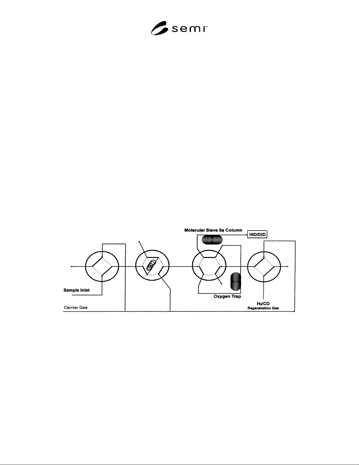
Figure 4
Analysis of Nitrogen and Argon in Oxygen Using Oxygen Trap
NOTICE: SEMI makes no warranties or representations as to the suitability of the standards set forth herein for any
particular application. The determination of the suitability of the standard is solely the responsibility of the user.
Users are cautioned to refer to manufacturer's instructions, product labels, product data sheets, and other relevant
literature, respecting any materials or equipment mentioned herein. These standards are subject to change without
notice.
By publication of this standard, Semiconductor Equipment and Materials International (SEMI) takes no position
respecting the validity of any patent rights or copyrights asserted in connection with any items mentioned in this
standard. Users of this standard are expressly advised that determination of any such patent rights or copyrights, and
the risk of infringement of such rights are entirely their own responsibility.
Copyright by SEMI® (Semiconductor Equipment and Materials
International), 3081 Zanker Road, San Jose, CA 95134. Reproduction of
the contents in whole or in part is forbidden without express written
consent of SEMI.
SEMI C3.6-0701 © SEMI 1981, 20011
SEMI C3.6-0701
SPECIFICATION FOR PHOSPHINE (PH
3
) IN CYLINDERS, 99.98%
QUALITY
This specification was technically approved by the Global Gases Committee and is the direct responsibility of
the North American Gases Committee. Current edition approved by the North American Regional Standards
Committee on April 30, 2001. Initially available at www.semi.org May 2001; to be published July 2001.
Originally published in 1981; previously published in 1995.
1 Description
1.1 Phosphine is a highly toxic, flammable, colorless
gas with an odor of decaying fish. In high
concentrations, it is pyrophoric. It is shipped as a liquid
in cylinders under its own vapor pressure.
2 Specifications
QUALITY: 99.98%
Impurities
Maximum Acceptable
Level (ppm)*
Arsine (AsH
3
)10
Carbon dioxide (CO
2
)10
Carbon Monoxide (CO) 1
Heavy Metals **
Hydrogen (H
2
) 100
Nitrogen (N
2
)50
Oxygen (O
2
) + Argon (Ar) 5
Particles **
Hydrocarbons expressed as
Methane (C
1
–C
2
)
4
Water (H
2
O) (v/v) 1
TOTAL LISTED IMPURITIES 181
* An analysis of significant figures has not been considered. The
number of significant figures will be based on analytical accuracy and
the precision of the provided procedure.
** To be determined between supplier and user.
3 Physical Constants (for in formation only)
Metric Units US Units
Molecular weight 33.997 33.997
Boiling point at 1 atm -87.7°C -125.9°F
Density of gas at 25°C
(77°F) and 1 atm
1.402 kg/m
3
0.0875 lb/ft
3
Specific gravity of gas
at 21.1°C (70°F) and 1
atm (air = 1)
1.146 1.146
Density of liquid at
boiling point
744 kg/m
3
46.45 lb/ft
3
4 Analytical Procedures
4.1 Carbon Monoxide, Carbon Dioxide, and
Hydrocarbons (expressed as methane) — This
procedure is for the determination of carbon monoxide,
carbon dioxide, and hydrocarbons in phosphine using a
gas chromatograph with a methanizer and a flame
ionization detector. (See Note 1 and Figure 1.)
4.1.1 Detection Limit — 0.1 ppm each impurity.
4.1.2 Instrument Parameters
4.1.2.1 Column — Porapak QS, 3.5 m (12 ft) by 3.2
mm (1/8 in) OD by 2.2 mm (0.085 in) ID ss or
equivalent.
4.1.2.2 Carrier Flow — 35 mL/min helium.
4.1.2.3 Support Gases
Hydrogen: 30 mL/min added to the carrier gas between
the column outlet and the methanizer inlet.
Air: 500 mL/min.
4.1.2.4 Temperatures:
Detector 110°C
Injector 40°C
Oven 40°C
Methanizer 370–400°C
4.1.2.5 Sample Volume — 3 mL.
4.1.3 Calibration Standards — 1–10 ppm each:
carbon monoxide, carbon dioxide, methane, ethane*,
ethylene*, and acetylene*, balance helium. *These
components are for reference only.
4.1.4 Operating Procedure
4.1.4.1 Inject the calibration standard into the column
using a gas sampling valve. Record retention times and
peak areas. Order of elution is carbon monoxide,
methane, carbon dioxide, acetylene, ethylene.
4.1.4.2 Inject the sample to be tested in the same
manner as the calibration standard. Vent the phosphine
after the ethylene peak. Record the retention times and
peak areas.
4.1.4.3 Repeat 4.1.4.1.