semi合集-English.pdf - 第205页
SEMI E26-92 © SEMI 1992, 2004 4 RELATED INFORMATION 1 NOTE: This related informatio n is not an official part of SEMI E26 but was reapproved for publication by full letter ballot procedures on February 28, 1999. R1-1 Alp…
SEMI E26-92 © SEMI 1992, 2004 3
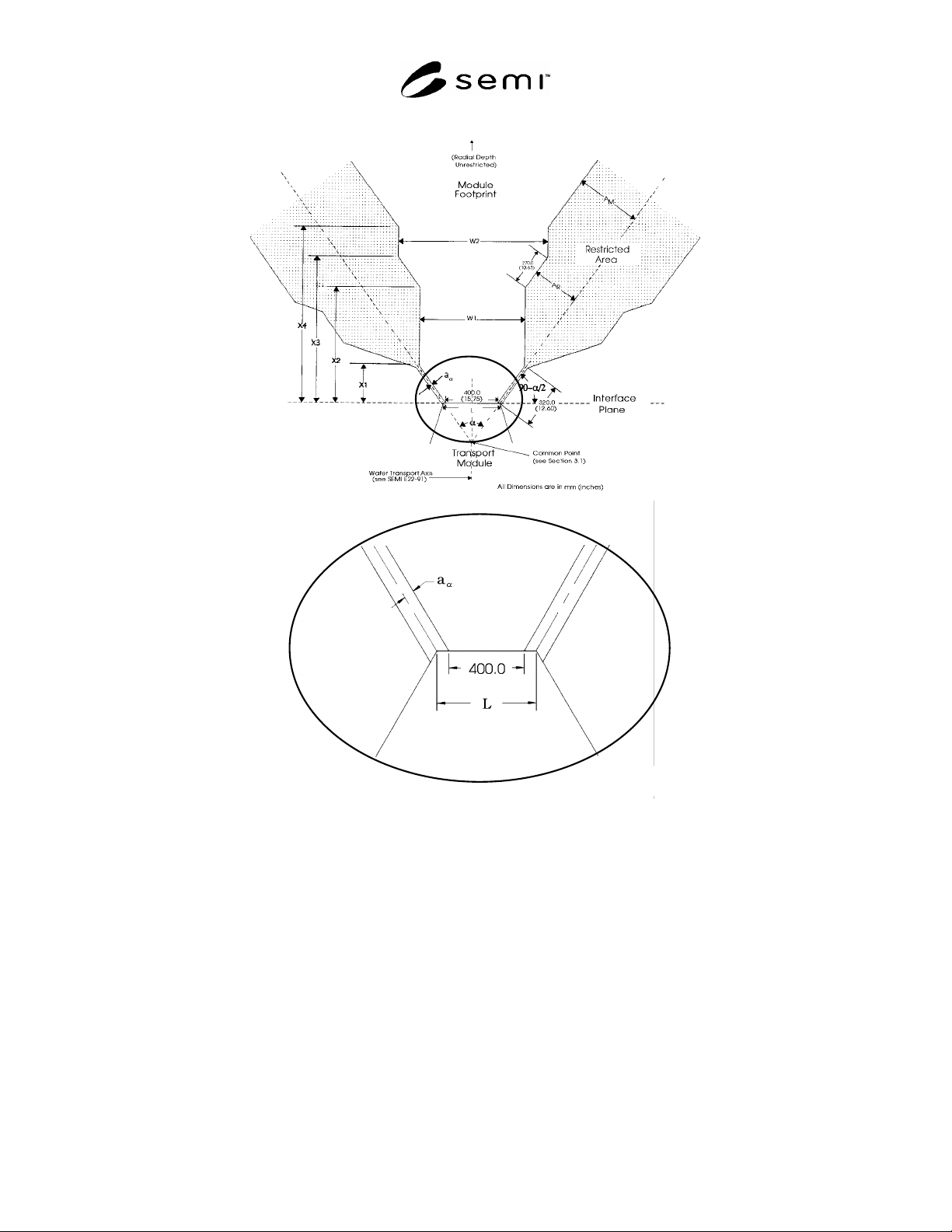
Figure 1
Radial Cluster Tool Module Footprint

SEMI E26-92 © SEMI 1992, 2004 4
RELATED INFORMATION 1
NOTE: This related information is not an official part of
SEMI E26 but was reapproved for publication by full letter
ballot procedures on February 28, 1999.
R1-1 Alpha Values
R1-1.1 A transport module in the shape of an N-sided
regular polygon possesses an alpha value of 360/N (see
Section 4.1 and Figure 1).
R1-2 Transport Module Side Length
R1-2.1 The specified transport module side length (L)
of 420 mm (16.54 in.) given in Table 2 is a minimum
value that will ensure clearance at the interface plane
valve (see SEMI E21), assuming a 340 mm (13.39 in.)
flange width at the interface plane plus additional
clearance for side-mounted clamps. The side length is
specified as a minimum value since a single transport
module could have various side lengths and/or alpha
values. Longer side lengths may ease access to the
transport module, but will have the negative impact of
increasing the transport module handler extension,
which is the distance from the common point (in Figure
1) to the wafer transport position (defined in SEMI
E22). For a radial cluster tool with the transport module
handler having the "home" position at the common
point, the maximum extension in millimeters is related
to the side length, alpha, and the transport maximum
reach, which is specified as 305 mm (12 in.) in SEMI
E21 by:
L
2
×
tan 90
–
2
305
R1-3 Evaluation of Footprint Shapes
R1-3.1 Access (see Section 4.1) for a variety of
purposes is severely restricted in a radial cluster tool,
because all modules converge toward one areR1-
Achieving access to clamps at the interface plane and to
the module (usually a process module) in proximity to
the interface plane is especially difficult. Thus, several
footprint shapes were modelled: A radial architecture
comprising an N-sided regular polygon transport
module with L = 420 mm (see Table 2 and Section R1-
2) was used, and the dimensional effects on the module
footprint were investigated for 4 N 10. Anatomical
data was used to evaluate access to various parts of the
radial cluster tool. The configuration chosen provides a
short, fat footprint. It allows maximum freedom for the
module designer and accommodates modules near the
interface plane without forcing the design of additional
wafer transport mechanisms. Guidance in setting W1
and W2 values (see Figure 1) was provided by the need
for a single wafer sputter module to be placed directly
on an N = 8 regular polygon transport module and a
batch processing module with an intermediate "buffer"
station on the same transport module.
R1-4 Module Width at Interface Plane
R1-4.1 Although L can be longer than 420 mm (16.54
in.), the module attached to the transport module cannot
possess a width greater than 400 mm (15.75 in.) at the
interface plane in order to be interchangeable among all
transport module interfaces (see Figure 1).
R1-5 Flexibility for Module Suppliers
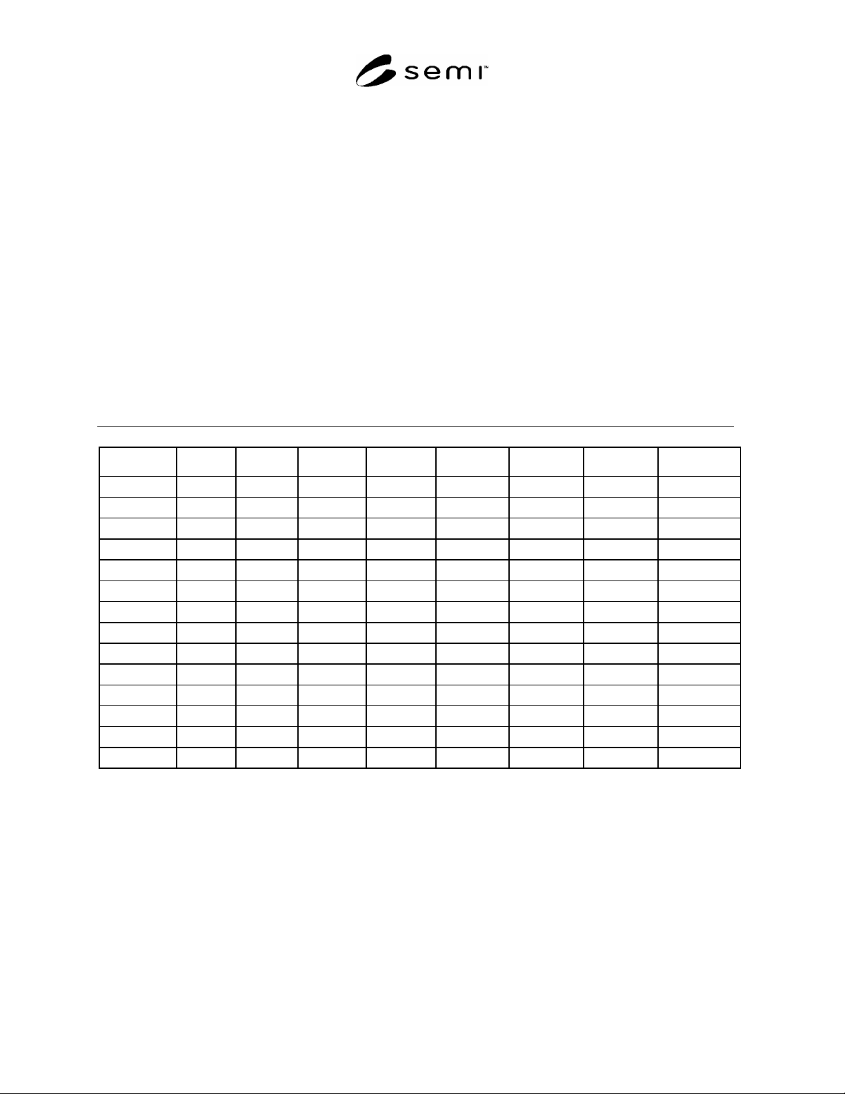
R1-5.1 Module footprint dimensions (calculated from
the expressions in Table 2) and transport module
handler extensions (calculated from the expression in
Section R1-2) for L = 420 mm and for selected values
of alpha are given in Table A1 to provide guidance for
weighing design targets. Alpha values corresponding to
values of N for an N-sided regular polygon transport
module are noted.
R1-5.2 Modules designed for an N = 8 ( = 45º)
transport module will fit on any transport module with
N 8 ( 45º), providing for greater flexibility, but
possessing a more restrictive footprint, than a module
designed for an N = 6 ( = 60º) transport module.
R1-6 Nonradial Cluster Tool Applicability
R1-6.1 An example of a nonradial transport module is
shown in Figure R1-1. Sides 1, 3, 4, and 5 of the
transport module are equivalent to a radial cluster tool.
The standard applies to these four sides (see Section
4.1).
R1-7 Restricted Areas
R1-7.1 Access (see Section 4.2) for maintenance
activities that involve the lifting of heavy components
or crouching, requires a minimum separation of 2 AM
= 915 mm (36 in.) between integrated module hardware
(see Table 2). When a width of 915 mm (36 in.) for the
entire restricted area was used in the model (see Section
R1-3), it became apparent that footprints would
comprise narrow corridors. This would force the design
of buffer chambers and additional wafer handling
mechanisms for many applications. For practical
purposes, the concept of a smaller reach area (the
hatched region in Figure R1-2), where the module
should be detached from the transport module for heavy
lifting or crouching tasks, was considered acceptable.
SEMI E26-92 © SEMI 1992, 2004 5
R1-7.2 Dependence on L — A transport module side
length (L) greater than the minimum value of 420.0 mm
will result in a larger restricted area by increasing the
half widths A
M
, A
R
, and a
beyond their respective
minimum values of 457.5 mm, 360.0 mm, and
10×cos[/2] mm (see Table 2).
R1-7.3 Restricted Area Temporary Residence —
Equipment such as roll-out drawers or swing-out
equipment may temporarily reside in the restricted area
(see Section 4.2).
R1-8 Restriction on Alpha
R1-8.1 The maximum value of alpha was based on an
N = 4 ( = 90º) regular polygon transport module
design (see Section 4.3).
R1-8.2 In order for a module manufacturer to
adequately design for access, some knowledge of the
adjacent modules must be available. This can be done
by setting a minimum value for alpha, which then
defines the adjacent footprint leading to the most
stringent "half" access area. For the purposes of the
standard, the minimum value of alpha was based on an
N = 10 ( = 36º) regular polygon transport module (see
Figure R1-2).
R1-9 Module Connect and Disconnect
R1-9.1 The number of components and the degree of
complexity at the interfaces of a radial cluster tool are
high. To ensure non-interference between modules, the
concept of an impenetrable wall at the interface plane
and adjacent module footprints should be used. Within
this area, requirements for module connect and
disconnect are the responsibility of the module
manufacturer (see Section 4.4).
Table R1-1 Module Footprint Dimensions and Transport Module Handler Extensions*
α(degrees)
a
α
(mm)
W1(mm) W2(mm) X1(mm) X2(mm) X3(mm) X4(mm) TMHE**(mm)
90 (N=4) 7.1 852.5 1234.4 226.3 725.4 916.3 1054.2 515.0
84 7.4 828.2 1188.6 237.8 764.7 965.4 1111.1 538.2
78 7.8 802.8 1142.6 248.7 808.4 1018.2 1173.1 564.3
72 (N=5) 8.1 776.2 1093.6 258.9 857.6 1076.0 1241.9 594.0
66 8.4 748.6 1042.7 268.4 914.0 1140.4 1319.4 628.4
60 (N=6) 8.7 720.0 990.0 277.1 979.8 1213.6 1408.6 668.7
56 8.8 700.5 954.0 282.5 1030.6 1269.0 1476.6 700.0
51.428 (N=7) 9.0 677.7 912.0 288.3 1097.3 1340.5 1585.2 741.1
48 9.1 660.3 879.8 292.3 1155.0 1401.6 1641.3 776.7
45 (N=8) 9.2 644.9 851.6 295.6 1212.2 1461.7 1716.5 812.0
42 9.3 629.4 822.9 298.7 1277.2 1529.3 1801.4 852.1
40 (N=9) 9.4 618.9 803.6 300.7 1325.8 1579.5 1864.6 882.0
38 9.5 608.4 794.2 302.6 1379.3 1634.5 1834.0 914.9
36 (N=10) 9.5 597.8 764.6 304.3 1438.5 1695.3 2010.8 951.3
* Calculated for L = 420 mm
** Transport Module Handler Extension