semi合集-English.pdf - 第5916页
SEMI P39-0304 E2 © SEMI 2004 19 Table 14 Standard Placement Values F angle X00 X01 X10 X11 0 0° +1 0 0 +1 1 0° +1 0 0 1 0 90° 0 +1 1 0 1 90° 0 +1 +1 0 0 180° 1 0 0 1 1 180° 1 0 0 +1 0 270° 0 1 +1 0 1 270° 0 …
SEMI P39-0304
E2
© SEMI 2004 18
22.2 In record type ‘17’, placement-info-byte contains the bit pattern ‘CNXYRAAF’.
22.3 In record type ‘18’, placement-info-byte contains the bit pattern ‘CNXYRMAF’.
22.4 When C = 1, the cell reference is explicit, in which case N = 1 means that reference-number (an unsigned-
integer) is present, and refers to a CELLNAME record where the cell name is stored; N = 0 means that cellname-
string (an n-string) is present and stores the cell name locally. When C = 0, N is ignored, and the value of modal
variable placement-cell is used, referring to the same cell as the previous PLACEMENT record.
22.5 x and y are signed-integer coordinates representing either the absolute or the relative (x,y) location of the
placement. X is 1 if x is present, and Y is 1 if y is present. When either x or y is unspecified, the value of modal
variable placement-x or placement-y, respectively, is used instead. Refer to Section 21 on page 17 for a discussion of
how absolute and relative modes affect the interpretation of x and y.
22.6 R is 1 if repetition is present. F = 1 indicates reflection (or flip) about the x-axis; F = 0 indicates no flip.
22.7 In record type ‘17’, magnification is 1.0 and rotation is a counterclockwise integral multiple of 90°: AA = 0 for
0°,
AA = 1 for 90°, AA = 2 for 180°, and AA = 3 for 270°.
22.8 In record type ‘18’, magnification and rotation are reals; angle is dimensioned in degrees, with positive values
denoting a counterclockwise rotation; magnification is, of course, unitless. A is 1 if angle is present, otherwise the
rotation defaults to 0°. M is 1 if magnification is present, otherwise the magnification defaults to 1.0.
22.9 Each successive PLACEMENT record updates all placement-related modal variables.
22.10 EXCEPTION HANDLING
— Use of a reference-number for which there is no corresponding CELLNAME
record should be treated as a fatal error. Any recursive cell reference (a cell placing a copy of itself within itself)
should be treated as a fatal error. Magnification values which are negative or zero should be treated as fatal errors.
Floating point values of NaN or Inf for either magnification or angle should be treated as fatal errors.
PLACEMENT records may refer to CELL records regardless of their relative location within the file, and may also
refer to external cells which are not defined in the same file.
23 Placement Transform Representation
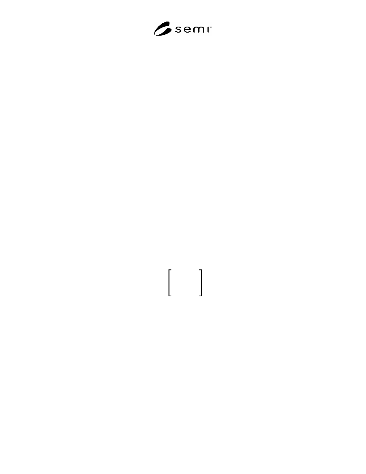
23.1 EDA applications generally define a placement transform as a 3×3 matrix:
T =
X00 X01 0
X10 X11 0
X20 X21 1
which transforms any point (p,q) via left-multiplication by the 1×3 row matrix [ p q 1 ]. Conversion of OASIS
placement data to this form is defined as follows:
X00 = cos( angle ) * magnification
X01 = sin( angle ) * magnification
X10 = -f * sin( angle ) * magnification
X11 = +f * cos( angle ) * magnification
X20 = x
X21 = y
where f = 1 if F = 0, f = -1 if F = 1, “angle” is the rotation angle given by either AA or angle in the PLACEMENT
record, and “magnification” is magnification if specified, else 1.0. Note that if the rotation is a multiple of 90° and
the magnification is 1.0, then the upper 2×2 sub-matrix takes one of the following eight forms and OASIS
processors may optimize accordingly:
SEMI P39-0304
E2
© SEMI 2004 19
Table 14 Standard Placement Values
F angle X00 X01 X10 X11
0 0° +1 0 0 +1
1 0° +1 0 0 1
0 90° 0 +1 1 0
1 90° 0 +1 +1 0
0 180° 1 0 0 1
1 180° 1 0 0 +1
0 270° 0 1 +1 0
1 270° 0 1 1 0
23.2 When repetition is present, the above transform is that of the first
element of the repetition. In general, the
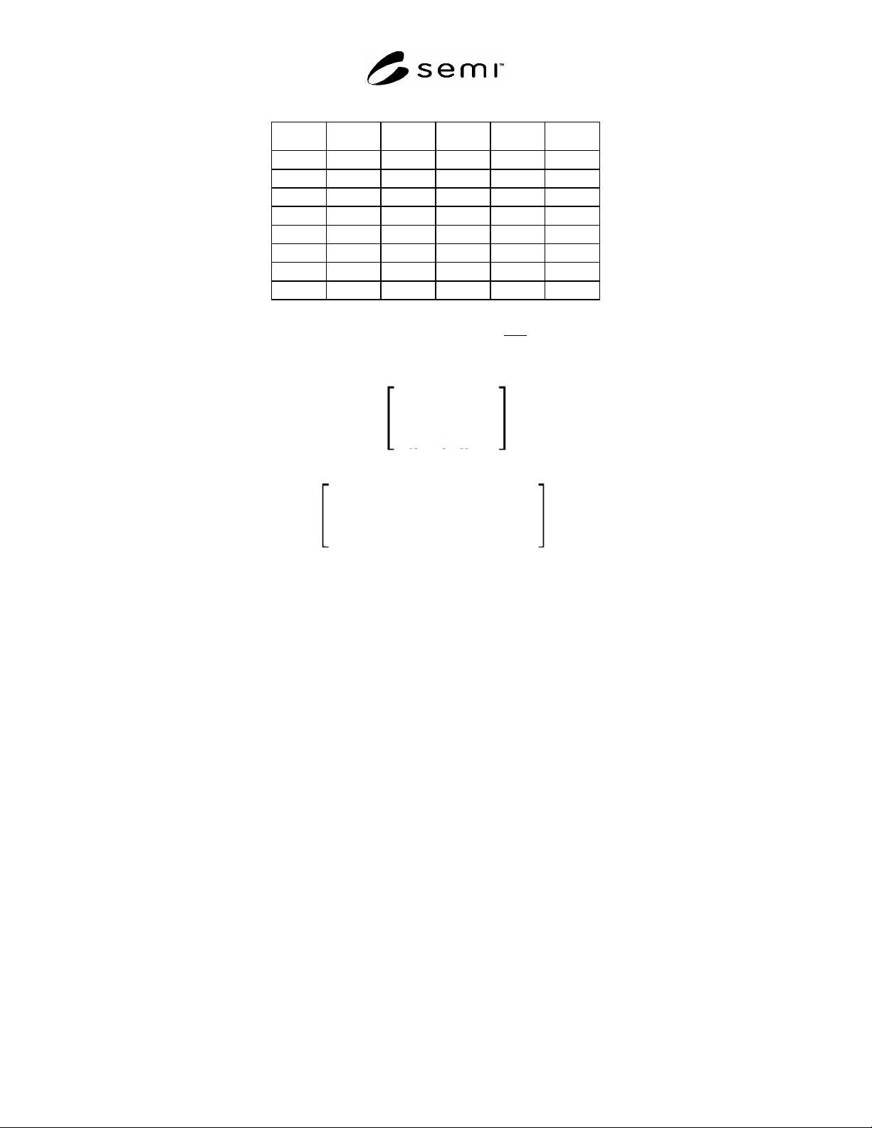
transform of any element E of the repetition is computed by right-multiplying the transform of the first element by
the matrix:
1
0
x-offset
0
1
y-offset
0
0
1
S =
to yield:
X00
X10
(X20 +
x-offset
)
X01
X11
(X21 +
y-offset
)
0
0
1
(Refer to Section 7.6.3 and subsequent paragraphs beginning on page 7 for a discussion of how x-offset and y-offset
are determined for the various repetition types.)
24 TEXT Record
24.1 A TEXT record represents a text element, consisting of an (x,y) coordinate point and an annotation string. It
has the following format:
‘19’ text-info-byte [ reference-number | text-string] [ textlayer-number ] [ texttype-number ]
[ x ] [ y ] [ repetition ]
24.2 The text-info-byte contains the bit pattern ‘0CNXYRTL’.
24.3 When C = 1, the text reference is explicit, in which case N = 1 means that reference-number (an unsigned-
integer) is present, and refers to a TEXTSTRING record where the text string is stored; N = 0 means that text-
string (an a-string) is present and stores the text string locally. When C = 0, N is ignored, and the value of modal
variable text-string is used instead.
24.4 x and y are signed-integer coordinates representing either the absolute or the relative (x,y) location of the text
element. X is 1 if x is present, and Y is 1 if y is present. When either x or y is unspecified, the value of modal
variable text-x or text-y, respectively, is used instead. Refer to Section 21 on page 17 for a discussion of how
absolute and relative modes affect the interpretation of x and y.
24.5 R is 1 if repetition
is present. L is 1 if textlayer-number is present. T is 1 if texttype-number is present.
Both textlayer-number and texttype-number are unsigned-integers. When textlayer-number and/or texttype-
number are unspecified, they assume the value of modal variables textlayer and texttype, respectively.
24.6 Each successive TEXT record updates all text-related modal variables.

SEMI P39-0304
E2
© SEMI 2004 20
24.7 EXCEPTION HANDLING — Use of a reference-number for which there is no corresponding
TEXTSTRING record within the same OASIS file should be treated as a fatal error. Implicit use of modal variables
textlayer or texttype when they are in the undefined state should be treated as a fatal error.
25 RECTANGLE Record
25.1 A RECTANGLE record represents a rectangular figure whose edges are parallel to the x- and y-axes. It has
the following format:
‘20’ rectangle-info-byte [ layer-number ] [ datatype-number ] [ width ] [ height ] [ x ] [ y ] [ repetition ]
25.2 The rectangle-info-byte contains the bit pattern ‘SWHXYRDL’.
25.3 R is 1 if repetition is present. L is 1 if layer-number is present. D is 1 if datatype-number is present. Both
layer-number and datatype-number are unsigned-integers. When layer-number and/or datatype-number are
unspecified, they assume the value of modal variables layer and datatype, respectively. W is 1 if width is present.
H is 1 if height is present. Both width and height are unsigned-integers. When width and/or height are
unspecified, they assume the value of modal variables geometry-w and geometry-h, respectively.
25.4 S is 1 if the rectangle is a square. In this case, H must be 0, and width, if present, is used for both dimensions
of the rectangle. When width is unspecified, the value of modal variable geometry-w is used instead.
25.5 x and y
are signed-integer coordinates representing either the absolute or the relative (x,y) location of the
lower-left corner of the rectangle. X is 1 if x is present, and Y is 1 if y is present. When either x or y is unspecified,
the value of modal variable geometry-x or geometry-y, respectively, is used instead. Refer to Section 21 on page 17
for a discussion of how absolute and relative modes affect the interpretation of x and y.
25.6 Each successive RECTANGLE record updates all rectangle-related modal variables. (When S = 1, both
geometry-w and geometry-h are set to the rectangle’s width.)
25.7 EXCEPTION HANDLING
— Implicit use of modal variables geometry-w, geometry-h, layer, or datatype
when they are in the undefined state should be treated as a fatal error. When S = 1, H = 1 should be treated as a fatal
error. The interpretation of zero-area RECTANGLEs is application-dependent.
26 POLYGON Record
26.1 A POLYGON record represents an arbitrary polygon figure. It has the following format:
‘21’ polygon-info-byte [ layer-number ] [ datatype-number ] [ point-list ] [ x ] [ y ] [ repetition ]
26.2 The polygon-info-byte contains the bit pattern ‘00PXYRDL’.
26.3 x and y are signed-integer coordinates representing either the absolute or the relative (x,y) location of the
initial vertex of the polygon. X is 1 if x is present, and Y is 1 if y is present. When either x or y is unspecified, the
value of modal variable geometry-x or geometry-y, respectively, is used instead. Refer to Section 21 on page 17 for a
discussion of how absolute and relative modes affect the interpretation of x and y.
26.4 R is 1 if repetition is present. L is 1 if layer-number is present. D is 1 if datatype-number is present. Both
layer-number and datatype-number are unsigned-integers. When layer-number and/or datatype-number are
unspecified, they assume the value of modal variables layer and datatype, respectively.
26.5 P
is 1 if point-list is present. Otherwise, the value of modal variable polygon-point-list is used. The format of
point-lists is defined in Section 7.7 on page 9.
26.6 Each successive POLYGON record updates all polygon-related modal variables.
26.7 EXCEPTION HANDLING
— Polygons with fewer than three vertices should be treated as fatal errors. Implicit
use of modal variables polygon-point-list, layer, or datatype when they are in the undefined state should be treated
as a fatal error. The interpretation of self-intersecting polygons, reentrant polygons, and polygons with zero-area
regions is application-dependent.