semi合集-English.pdf - 第6015页
SEMI G1-96 © SEMI 1 980, 199 6 8 Figure 8

SEMI G1-96 © SEMI 1980, 19967
9.4.6.2 Voids or Pits — Exposure of base metal with
any dimension greater than 0.001" (0.025 mm).
9.4.6.3 Discoloration, Blistering, or Peeling of the
Metallization
9.4.6.4 Scratches or Scrapes — Any b uild-up of
metallization or exposure of base metal.
9.4.6.5 Foreign Material, Including Glass Splatter or
Projections — No more than three sites, each with a
maximum dimension in any plane of 0.001" (0.025
mm).
9.4.7 Mechanical Damage — Leads
9.4.7.1 Broken, Kinked, or Missing Leads
9.4.7.2 Twist — Any lead twisted by more than 10°
from the untwisted condition.
9.4.7.3 Bottom-Formed Width — Any sub-assembly
with the bottom-formed width of the leadframe
exceeding ± 0.010" (0.254 mm).
9.4.7.4 Top-Formed Width — Any sub-assembly with
the top-formed width of the leadframe exceeding ±
0.010" (0.254 mm).
10 Incoming Inspection and Functional Tests
10.1 Incoming Inspection
10.1.1 Dimensional Inspection per Section 7.
10.1.2 Visual inspection per Section 9 at 10×
magnification with vertical lighting.
10.1.3 Metallization
10.1.3.1 Die-Attach Metallization — Thickness shall
be measured by standard cross-sectioning without
smearing or by X-ray fluorescence.
10.1.3.2 Lead Bond Metallization — Thickness shall
be measured by X-ray fluorescence.
10.1.3.3 External Lead Plating (If Applicable) —
Thickness shall be measured by X-ray fluorescence.
10.1.4 Lead Solderability (If Applicable) — Tested in
accordance with MIL-STD-883, Method 2003.
10.2 Functional Testing
NOTE 9: All procedures to functionally test the components
or sub-assemblies shall be agreed upon between user and
supplier.
The sequence of functional testing (and subsequent
environmental testing) shall be as shown in Figure 8.
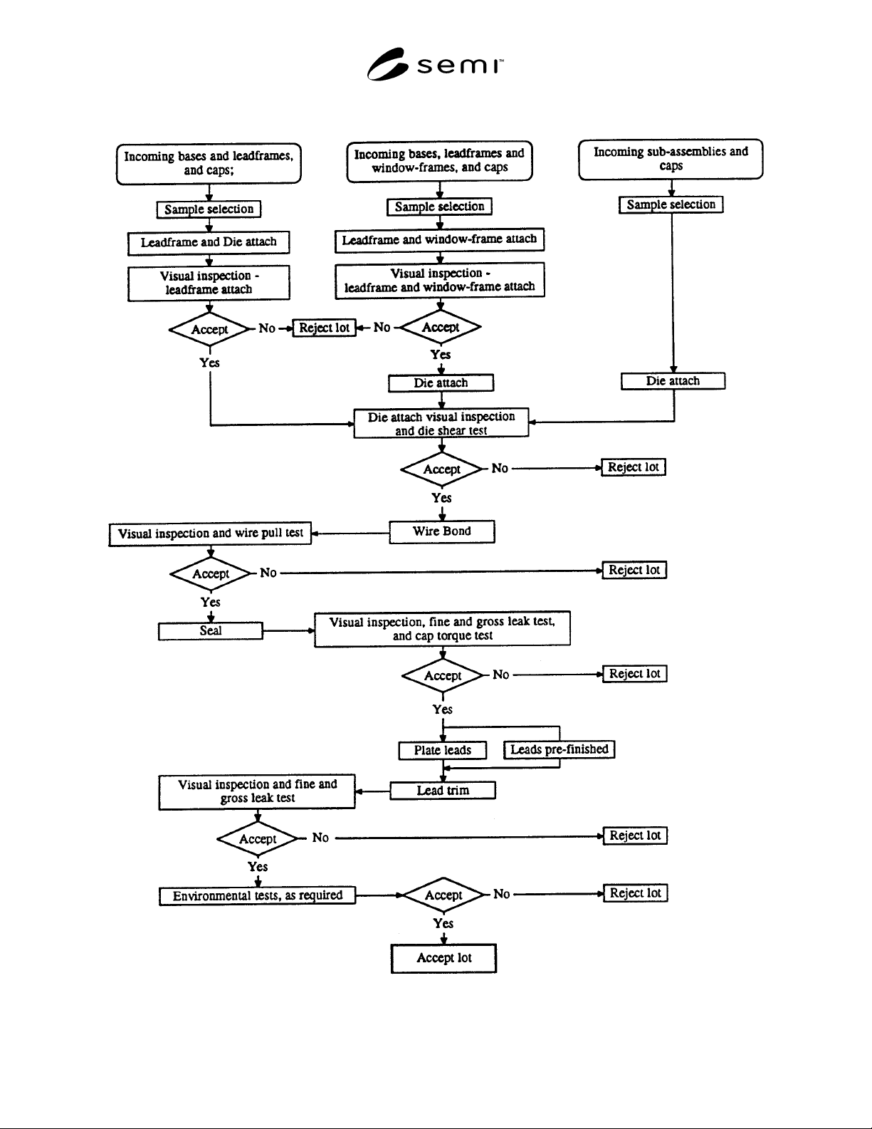
SEMI G1-96 © SEMI 1980, 1996 8
Figure 8

SEMI G1-96 © SEMI 1980, 19969
10.2.1 Die Attach
10.2.1.1 Visual Inspection
• Eutectic Bonding — Visually inspect the alloy wet-
out after die attach. The minimum wet out
requirement shall be 100% of the die perimeter.
• Silver Glass or Resin Bonding — 100% die
perimeter coverage shall be required.
NOTE 10: 100% coverage for silver glass or resin bonding is
not a function of base acceptability but is required to
standardize die shear testing. The inability of the resins to wet
the surface of the die attach area due to contamination is
cause for rejection.
10.2.1.2 Die Shear Test — Perform destructive testing
in accordance with MIL-STD-883, Method 2019.
NOTE 11: Test may also be performed after environmental
testing. In the case of very large die, this test may not be
appropriate to fully evaluate the package. In these cases, die
sizes agreed upon between user and supplier shall be used.
Alternatively, die pull testing may be used by agreement
between user and supplier. Inspection for die attach voids may
be performed radiographically in accordance with Section
10.2.1.3 in order to ensure that the die attach process does not
contribute to an incorrect evaluation of the shear or pull test
results. In the case of eutectic die attach, the results from
these methods may also be indicative of poor functionality of
the gold die-attach metallization.
10.2.1.3 Void Inspection — Inspection for die-attach
voids may be performed radiographically in accordance
with MIL-STD-883. Method 2012 or ultrasonically in
accordance with MIL-STD 883, Method 2030.
10.2.2 Wire Bond — On wire bonds which meet the
requirements of MIL-STD-883, Method 2010, perform
destructive pull testing in accordance with MIL-STD-
883, Method 2011, Test Condition D.
NOTE 12: Bonds which cause lifted metallization from the
lead fingers shall also be cause for rejection.
NOTE 13: This test may be performed at pre seal and post-
seal.
10.2.3 Seal
10.2.3.1 Visual Inspection — The glass sealant
appearance and flow shall be visually inspected for
conformance to criteria agreed upon between user and
supplier.
10.2.3.2 Hermeticity — Performed in accordance with
MIL-STD-883, Method 1014, Test Condition A or B
and C, the package must maintain hermetic integrity
after each environmental test or sequence of tests.
NOTE 14: Internal water-vapor content may also be measured
in accordance with MIL-STD-883, Method 1018.
10.2.3.3 Cap Torque Test — The failure criteria shall
be agreed upon between user and supplier.
10.2.4 Lead Finish — Plate according to a process
agreed upon between user and supplier.
10.2.5 Lead Trim
10.3 Environmental Testing — Environmental
evaluation shall include, but not be limited to, the
following tests:
NOTE 15: The sequence of testing and the sample sizes for
each sub-group shall be agreed upon between user and
supplier.
10.3.1 Temperature Cycle — In accordance with MIL-
STD-883, Method 1010, Condition C.
10.3.2 Thermal Shock — Per MIL-STD-883, Method
1011, Condition B.
10.3.3 Vibration Fatigue — In accordance with MIL-
STD-883, Method 2005, Test Condition B.
10.3.4 Mechanical Shock — In accordance with MIL-
STD-883, Method 2002, Test Condition B.
10.3.5 Constant Acceleration — In accordance with
MIL-STD-883, Method 2001, Test Condition A.
10.3.6 Moisture Resistance — In accordance with
MIL-STD-883, Method 1004.
10.3.7 Additional Testing — Additional tests
performed during package qualification may include
evaluation of electrical and thermal characteristics,
corrosion resistance and alpha particle emissions. These
tests may be performed on a periodic basis to maintain
package qualification. These tests may include, but are
not limited to, the following:
10.3.7.1 Insulation Resistance — In accordance with
MIL-STD-883, Method 1003, to test conditions agreed
upon between user and supplier.
10.3.7.2 Lead Inductance — In accordance with SEMI
G23 or using an impedance analyzer by a method
agreed upon between user and supplier.
10.3.7.3 Lead-to-Lead Capacitance — Per SEMI G24.
10.3.7.4 Lead Resistance — Per SEMI G25.
10.3.7.5 Junction-to-Case Thermal Resistance — In
accordance with SEMI G30 or a wind tunnel method
agreed upon between user and supplier.
10.3.7.6 Alpha particle emission shall be tested by a
method and to limits agreed upon between user and
supplier.
10.3.7.7 Salt Atmosphere (Corrosion) Testing — In
accordance with MIL-STD-883, Method 1009,