semi合集-English.pdf - 第219页
SEMI E31-93 © SEM I 1993 1 SEMI E31-93 SPECIFICA TION FOR ELECTRICAL INTERFAC E, JAPAN ONLY NOTE: For U.S. electrical interface requirements, s ee SEMI E7. 1 Introduction 1.1 Pur pose — The pu rpose of thi s st andard is…
SEMI E29-93 © SEMI 1993, 2004 2
comparison. It is defined for use in the semiconductor
industry as 101.32 kilo pascals (760 torr).
5.1.11 standard temperature — the temperature, in
degrees Celsius, specified as a reference for
measurement and comparison. It is defined for use in
semiconductor industry as 0.0°C.
5.1.12 standard volumetric flow — for mass flow
controllers and mass flow meters, the calculated
volumetric flow, at standard temperature and pressure,
of gas in a closed fluid channel. Volume at standard
temperature and pressure assumes the ideal gas law,
PV = nRT. Units of standard volumetric flow are
commonly used to express mass flow in mass flow
controllers and mass flow meters.
5.1.13 surrogate gas — for mass flow controllers and
mass flow meters, a gas intended to simulate the
calibration characteristics of another gas.
5.1.14 transfer standard — for mass flow controllers
and mass flow meters, a device typically calibrated
against a primary standard which can guarantee
sufficient accuracy to, in turn, calibrate another device.
5.1.15 warm-up time — for mass flow controllers and
mass flow meters, the time required, after going from
an unpowered to a powered state, for the device to
achieve sufficient electrical and thermal stability such
that rated performance specifications can be met.
NOTICE: SEMI makes no warranties or
representations as to the suitability of the standards set
forth herein for any particular application. The
determination of the suitability of the standard is solely
the responsibility of the user. Users are cautioned to
refer to manufacturer's instructions, product labels,
product data sheets, and other relevant literature,
respecting any materials or equipment mentioned
herein. These standards are subject to change without
notice.
By publication of this standard, Semiconductor
Equipment and Materials International (SEMI) takes no
position respecting the validity of any patent rights or
copyrights asserted in connection with any items
mentioned in this standard. Users of this standard are
expressly advised that determination of any such patent
rights or copyrights, and the risk of infringement of
such rights are entirely their own responsibility.
Copyright by SEMI® (Semiconductor Equipment and Materials
International), 3081 Zanker Road, San Jose, CA 95134. Reproduction of
the contents in whole or in part is forbidden without express written
consent of SEMI.
SEMI E31-93 © SEMI 19931
SEMI E31-93
SPECIFICATION FOR ELECTRICAL INTERFACE, JAPAN ONLY
NOTE: For U.S. electrical interface requirements, see SEMI E7.
1 Introduction
1.1 Purpose — The purpose of this standard is to
ensure common electrical interfaces that fulfill the
requirements of equipment suppliers and users in the
Japan region and to ease the design and functionality of
semiconductor equipment manufacturing facilities in
the future.
1.2 Scope — This standard recommends electrical
interfaces for selected power supplies as follows:
— Facilities-Systems Motors and electrical loads
having various voltages, currents, and phases
— Electrical connectors
— Cords/cables
2 Referenced Documents
2.1 JIS-C-8303 — Japanese Industrial Standard
1
2.2 JCS 168C-73 — Japanese Cable Standard
2
JEAC-78 — Japanese Electrical Association
Committee
3
3 Facilities
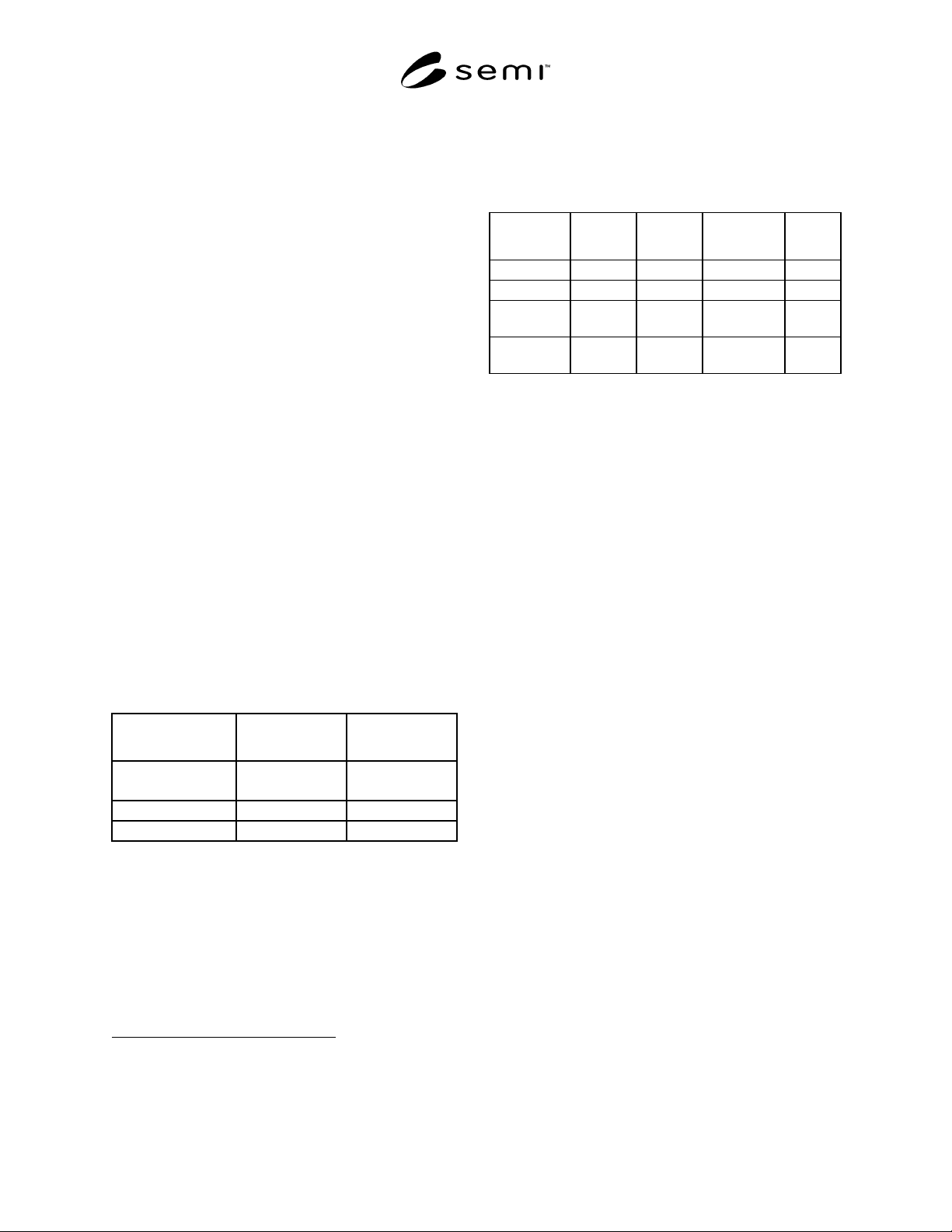
3.1 Motor
Power (W) Phase/Voltage
JEAC-78 Specified
Current (A)
35 to 400 1P 100 V
1P 200 V
2.2 to 9.5
1.1 to 4.4
200 to 3700 3P 200 V 1.8 to 17.4
200 to 7500 3P 400 V 0.9 to 17
Note: Specified currents are 0.9 times each current,
respectively, in the case of 110 V/220 V/440 V. Direct current
motors are excluded.
3.2 Voltage, Current, and Phase of Electrical Loads
(for calculation)
1 Japan Standard Association, 4-1-24 Akasaka, Minato-ku, Tokyo
2 Japan Cable Industry Association, 1-12-22 Tsukiji, Chuo-ku, Tokyo
3 Japan Electrical Association, 1-7-1 Yurakucho, Chiyoda-ku, Tokyo
Power (W) 1P 100V 1P 200V 3P 200V
JEAC-78
3P 400V
0 to 3000 0 to 30A 0 to 15A 0 to 8.7A
3000 to 5000 15 to 25A 8.7 to 14.5A
5000 to
30000
14.5 to 87A
30000 or
more
88A or more 44A or
more
Note: Specified currents are 0.9 times each current
respectively, in the case of 110V/220V/440V.
SEMI E31-93 © SEMI 1993 2
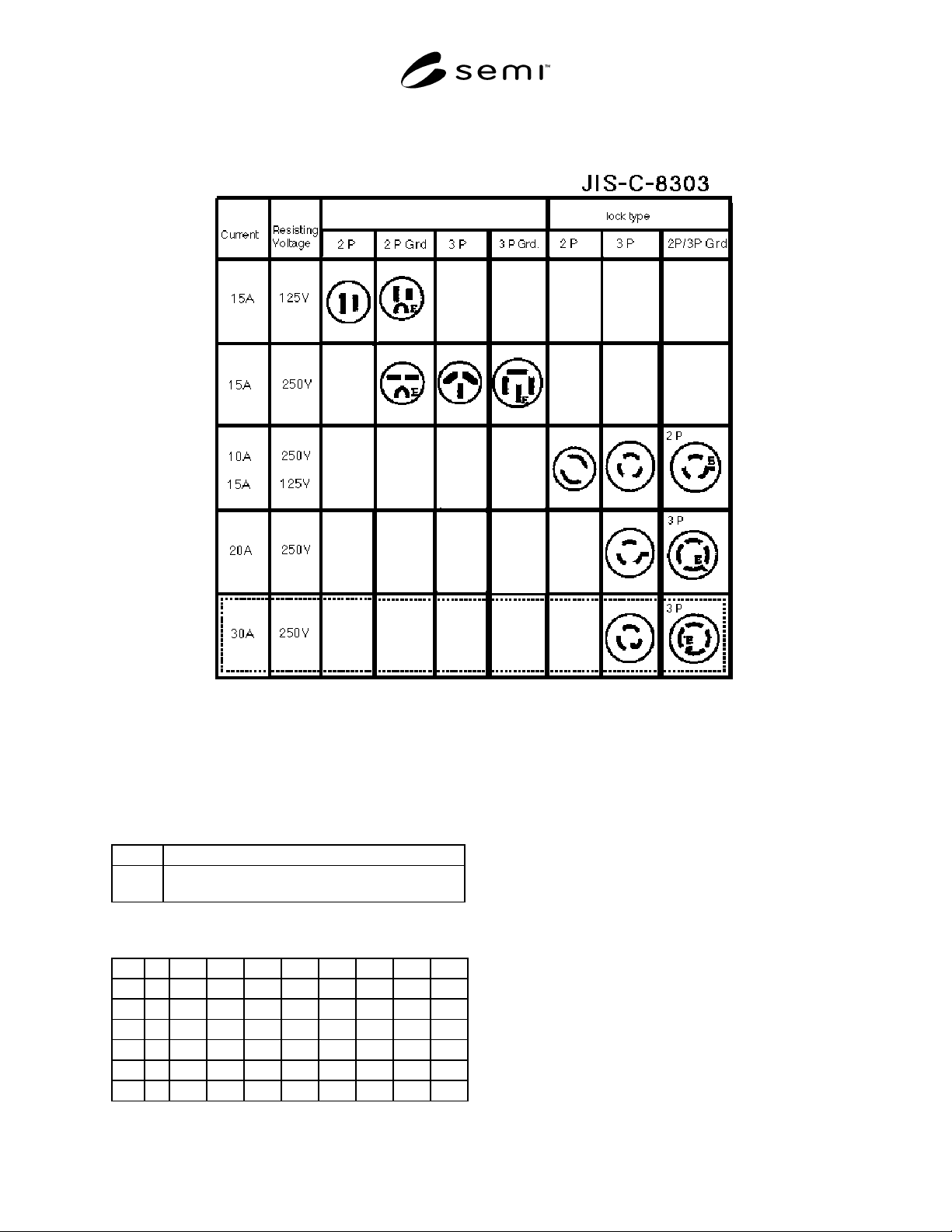
4 Electrical Connectors (sh own as receptacle)
Note: Direct terminal connections are used for most fixed facilities and loads, which require higher current than the value
specified above. 30A/250V shows at reference which is specified by the NEMA standards L6-30R and L15-30R.
5 Cable Current Tolerances
Key:
VV Vinyl insulation, vinyl sheathed cable
CV Construction polyethylene insulation, vinyl sheathed
cable
JCS 168C-73 Unit (A)
1.0Ø 2.0Ø 2sq 3.5sq 5.5sq 8sq 14sq 22sq
VV*1114192838476791
** 10 12 18 25 33 42 60 79
*** 9 10 15 22 29 37 53 70
CV*162333465974105135
** 17 20 28 40 52 66 94 125
***14172434455679105
* Single Conductor Three Cables
** Twin Conductors One Cable
*** Three Conductors One Cable
Note: The above specification is for cable in conduit in air.
Current tolerance of CV is different than that of VV due to the
difference in temperature tolerances (VV/60°C and
CV/90°C).
Ø: Diameter of Conductor (mm)
Sq: Cross-Sectional Area of Conductor (mm2)