semi合集-English.pdf - 第6223页
SEMI G45-93 © SEMI 198 6, 1993 4 NOTICE: T hese standards do n ot purport to address safety issues, if any, as sociated with their use. It is the responsibility of the user of these sta ndards to establish appropriate sa…
SEMI G45-93 © SEMI 1986, 19933
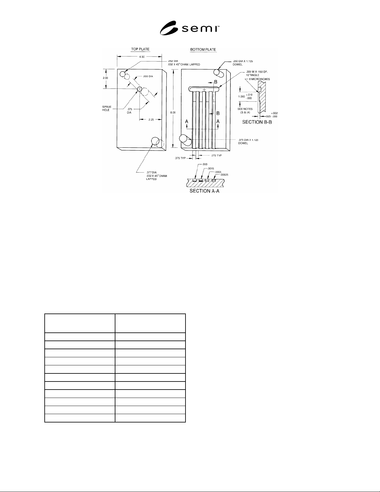
Figure 1
Flash Test Mold
1. Hand Mold, Polished, Very Well Mated Surfaces, Base Plates 0.75 thk.
2. Mold: Common Runner Feeds Flash Channels of 0.003, 0.0015, 0.0005, and 0.00025 inches by 0.375 wide ±
0.00025.
3. Mold Flash Channels: Surface Finish 8 microinches
4. Mold Flash Channels Depth Tolerance:
a. ± 0.00005" for 0.00025 and 0.0005: Channels
b. ± 0.0002" for 0.0015 and 0.003 Channels
AUXILIARY INFORMATION
Conversions
Inches
Conversions
Millimeters
8.000 203.20
4.500 114.30
2.250 57.15
2.000 50.80
1.125 28.58
1.000 25.40
0.377 9.58
0.375 9.53
0.300 7.62
0.252 6.40
0.250 6.35

SEMI G45-93 © SEMI 1986, 1993 4
NOTICE: These standards do not purport to address
safety issues, if any, associated with their use. It is the
responsibility of the user of these standards to establish
appropriate safety and health practices and determine
the applicability of regulatory limitations prior to use.
SEMI makes no warranties or representations as to the
suitability of the standards set forth herein for any
particular application. The determination of the
suitability of the standard is solely the responsibility of
the user. Users are cautioned to refer to manufacturer’s
instructions, product labels, product data sheets, and
other relevant literature respecting any materials
mentioned herein. These standards are subject to
change without notice.
The user’s attention is called to the possibility that
compliance with this standard may require use of
copyrighted material or of an invention covered by
patent rights. By publication of this standard, SEMI
takes no position respecting the validity of any patent
rights or copyrights asserted in connection with any
item mentioned in this standard. Users of this standard
are expressly advised that determination of any such
patent rights or copyrights, and the risk of infringement
of such rights, are entirely their own responsibility.
Copyright by SEMI® (Semiconductor Equipment and Materials
International), 3081 Zanker Road, San Jose, CA 95134. Reproduction o
f
the contents in whole or in part is forbidden without express written
consent of SEMI.

SEMI G46-88 © SEMI 19881
SEMI G46-88
TEST METHOD FOR THERMAL TRANSIENT TESTING FOR DIE
ATTACHMENT EVALUATION OF INTEGRATED CIRCUITS
1 Introduction
1.1 Purpose — Evaluation of sem iconductor die
attachment integrity using the thermal transient
techniques as implemented by the Electrical Test
Method on either thermal test chips or active devices.
1.2 Rationale — Steady state thermal response (or
thermal resistance) and thermal transient response of
discrete semiconductor devices and integrated circuits
are sensitive to the presence of voids in the die
attachment material between the semiconductor chip
and package. These voids impede the flow of heat from
the chip to the substrate (package). Due to the
difference in the thermal time constants of the chip and
package, the measurement of transient thermal response
can be made more sensitive to the presence of voids
than can the measurement of steady state thermal
response. This is because the chip thermal time constant
is generally several orders of magnitude shorter than
that of the package. Thus, the heating power pulse
width can be selected so that only the chip and the chip
to substrate interface are heated during the pulse by
using a pulse width somewhat greater than the chip
thermal time constant, but less than that of the
substrate. Heating power pulse widths ranging from 10
to 400 milliseconds have been found to satisfy this
criterion. This enables the detection of voids to be
greatly enhanced, with the added advantage of not
having to heat sink the device under test. Thus, the
transient thermal response technique is less time
consuming than the measurement of thermal resistance
for use as a manufacturing screen, process control or
incoming inspection measure for die attachment
integrity evaluation.
1.3 References — The following documents are
recommended reading for reference and test method
standard description purposes:
SEMI G32 — Unencapsulated Thermal Test Chip
MIL-STD-883C
1
— Method 1012, Thermal
Characteristics
2 Definitions
The following symbols and terminology shall apply for
the purpose of this test method.
1 Military Standards, Naval Publications and Form Center, 5801
Tabor Avenue, Philadelphia, PA 19120
2.1 V
F
— the forward biased volta ge of the diode
junction within the Device-Under-Test (DUT) used for
junction temperature sensing.
2.2 V
Fi
— the initial V
F
value befo re application of
heating power.
2.3 V
Ff
— the final V
F
value after application of
heating power.
2.4 ∆V
F
— the change in the temp erature sensitive
parameter, V
F
, due to the application of heating power
to the DUT.
2.5 V
H
— the voltage applied to the DUT during the
heating time in order to cause power dissipation.
2.6 I
H
— the heating current result ing from the
application of V
H
to the DUT.
2.7 P
H
— the heating power pulse magnitude; product
of V
H
and I
H
.
2.8 t
H
— the duration of P
H
(applie d to the DUT).
2.9 I
M
— the measurement current used to forward
bias the temperature sensing diode junction for
measurement of V
F
.
2.10 t
MD
— measurement delay time can be defined in
one of two ways:
2.10.1 the time from the start of heating power (P
H
)
removal to the completion of the final V
F
measurement;
or
2.10.2 the time from the start of heating power (P
H
)
removal to the start of the final V
F
measurement time,
referred to as t
SW
.
2.11 t
SW
— sample window time du ring which final
VF measurement is made; applicable only if t
MD
definition 2.10.2 is used.
2.12 K — the temperature-sensitive parameter
temperature coefficient measured at IM in °C per
millivolt.
2.13 CU — the comparison unit consisting of ∆V
F
divided by I
H
, that is used to normalize the transient
thermal response for variations in power dissipation; in
units of mV/A.
2.14 T
J
— the device-under-test junction temperature.
2.15 ∆T
J
— the change in T
J
caused by the application
of P
H
for a time equal to t
H
.