semi合集-English.pdf - 第2008页
SEMI E54.7-0999 © SEMI 1999 2 4.2 Other Documents Bulle tin No. 8310 PD9603 — Seri plex Stan dard Specificat io n: Au gust 1997, Techn ology Organizati o n, Inc. Raleigh, NC, USA. 1 ISO 7498 — Basic R eference Model for …

SEMI E54.7-0999 © SEMI 19991
SEMI E54.7-0999
STANDARD FOR SENSOR/ACTUATOR NETWORK COMMUNICATION
FOR SERIPLEX
This standard was technically approved by the Global Information & Control Committee and is the direct
responsibility of the North American Information & Control Committee. Current edition approved by the
North American Regional Standards Committee on July 15, 1999. Initially available at www.semi.org
August 1999; to be published September 1999.
1 Purpose
1.1 This standard defines a communication
specification based on the Seriplex protocol to enable
communications between intelligent devices on a
sensor/actuator network (SAN) that operate according
to SEMI specified device models (common and device
specific) in a semiconductor manufacturing tool.
1.2 Background and Motivation
1.2.1 Seriplex is a component level network which
provides a simple, inexpensive, fast, and deterministic
means of exchanging data among control level
industrial devices (e.g., sensors and actuators) and
higher level devices such as controllers. Seriplex
provides:
• A solution to low-level device networking
• Access to intelligence present in low-level devices
• Networking between higher level controllers
• Master/Slave and Peer-to-Peer capabilities
1.2.2 Seriplex specifies a communication model and
protocol as well as a complete Physical Layer
definition.
1.2.3 This document enables commu nications between
intelligent devices on a SEMI compliant SAN by
providing a presentation mapping of common and
specific device network visible structure and behavior
to a Seriplex network.
2 Scope
2.1 This document specifies the protocol and services
that compliant intelligent devices must support to
exchange information over this semiconductor
equipment sensor/actuator network.
2.2 This document specifies the utilization of the
Seriplex protocol to present externally visible device
structure and behavior, specified in the Common
Device Model (CDM) and appropriate Specific Device
Models (SDMs), on a Seriplex network.
2.3 This document is used in conjunction with a SEMI
standard SAN Common Device Model specification,
one or more SEMI standard Specific Device Model
(SDM) specifications (e.g. for a mass flow controller)
and the Seriplex Standard Specification. Together, they
describe the Seriplex protocol, the externally visible
data structures and behaviors of devices utilizing the
Seriplex networking capability in a SEMI compliant
SAN system.
2.4 This standard does not purport to address all of the
safety issues associated with its use. It is the
responsibility of the users of this standard to establish
appropriate safety and health practices and determine
the applicablity of regulatory limitations prior to use.
3 Limitations
3.1 This document specifies a semiconductor
equipment SAN based solely on Seriplex and is a
companion document to the Seriplex standard
specification; thus a complete specification of this
standard necessarily includes the Seriplex standard
specifications. There are other semiconductor
equipment SAN communications options. The
specifications for these options are not included here.
3.2 This standard specifies enhancements that provide
additional capabilities over and above those currently
required by Seriplex. In order to avoid document
consistency problems, information in the Seriplex
standard specification that relates to this standard is not
repeated in this document. This document is limited to
describing enhancements or limitations to the Seriplex
standard specification that are imposed by this standard.
4 Referenced Standards
4.1 SEMI Standards
SEMI E54.1 — Standard for Sensor/Actuator Network
Common Device Model
SEMI E54.3 — Specification for Sensor/Actuator
Network Specific Device Model for Mass Flow Device
SEMI E54.7-0999 © SEMI 1999 2
4.2 Other Documents
Bulletin No. 8310PD9603 — Seriplex Standard
Specification: August 1997, Technology Organization,
Inc. Raleigh, NC, USA.
1
ISO 7498 — Basic Reference Model for Open Systems
Interconnection
2
NOTE 1: As listed or revised, all documents cited shall be the
latest publications of adopted standards.
5 Terminology
5.1 Terminology that is common to all of the
documents in this SAN standard may also be defined in
the Sensor/Actuator Network Standard. Terminology
may be reproduced here which is defined in other SEMI
documents.
5.2 Abbreviations and Acronyms
CDM — Common Device Model
DM — Device Manager (object)
NCS — Network Communication Standard
OSI — Open Systems Interconnect
OSS — Object Services Standard
SAC — Sensor, Actuator, Controller (Object)
SAN — Sensor/Actuator Network
SDM — Specific Device Model
STO — Seriplex Technology Organization
VDC — Volts, Direct Current
5.3 Device Component Definitions
5.3.1 As this standard defines the presentation or
mapping of CDM data structure and behavior over a
network, it makes use of many of the terms in the SEMI
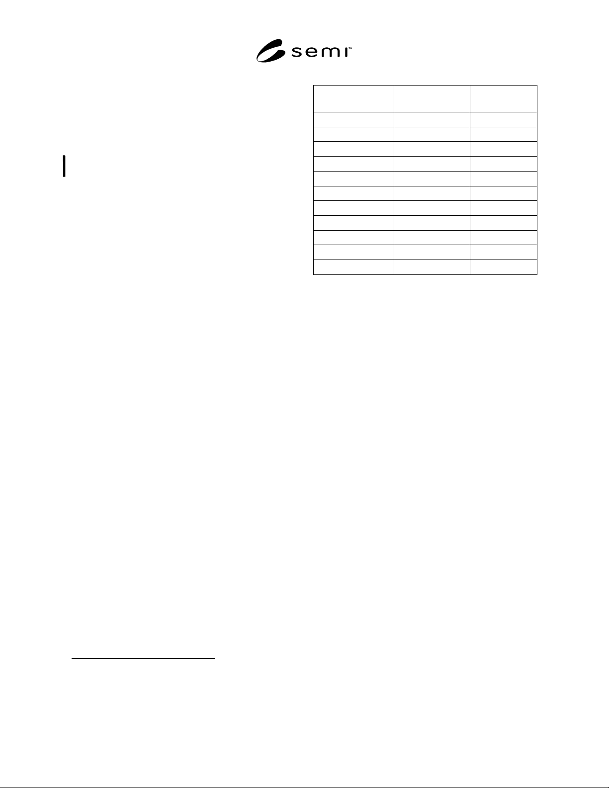
E54.1 CDM document. Table 1 provides a mapping of
fundamental terminology of the CDM document into
this document and the Seriplex standard specification.
Note that Column 2 contains an equal sign ‘=’ if the
definition is used exactly as specified in the CDM
specification.
1 Seriplex Technology Organization, P.O. Box 27446, Raleigh, NC
27611, www.seriplex.org
2 ISO Central Secretariat, 1, rue de Varembé, Case postale 56, CH-
1211 Genève 20, Switzerland
Table 1 Mapping of CDM to NCS Terminology
CDM Term NCS Equivalent Seriplex
Equivalent
Device = =
Device Model = =
Object =, Class =, Class
Instance = =
Attribute = =
Behavior = =
Service = =
State Diagram = =
Byte = =
Nibble = =
Character String ==
5.4 Seriplex Specific Definitions
class — a set of objects that all represent the same kind
of system component. A class is a general-ization of an
object. All objects in a class are identical in form and
behavior, but may contain different attri-bute values.
master/slave mode — communication over a Seriplex
network that provides exclusive control of data by a
“master” or “host” device. All bus input data is reported
exclusively to the host, and the host has exclusive
control over the states of all bus output signals, with all
bus I/O devices acting as ‘slaves”. Master/Slave mode
provides the typical request/ response oriented network
communications.
peer-to-peer mode — communication over a Seriplex
network that provides sharing of bus input and output
data directly among devices. This mode allows
dedicated or broadcast data to be shared between a
producing application and one or more consuming
applications. Application specific I/O data moves
though these devices.
seriplex — an open protocol maintained by the Seriplex
Technology Organization (STO) as a standard means of
interconnection for simple field devices. The Seriplex
standard specification specifies OSI reference model
layers 1, 2, 4 and 7 specifically the physical signaling,
the media access/data link protocols, the transport
capability of end-to-end transmission of data, and the
application layer.
6 Communication Protocol H igh Level
Structure
6.1 The Seriplex protocol is loosely based on a four-
layer architecture. These layers constitute a collapsed
form of the OSI seven layer architecture, mapping into
the physical, data link, transport and application layers
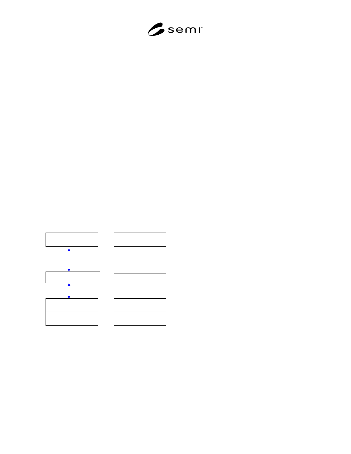
SEMI E54.7-0999 © SEMI 19993
of the Reference Model. The high level protocol
architecture is shown in Figure 1.
6.1.1 Note that Figure 1 represents a conceptual view
of the device architecture. Conforming implementations
must implement the services defined in this
specification at each layer and must appear (from the
network) to have implemented this architecture,
however an internal modular partitioning is not
required. Implementations may sacrifice modularity in
order to achieve high performance.
6.1.2 The Seriplex physical layer is fully specified in
the Seriplex Standard Specification. There are guideline
specified for the topology of the bus cable, length of
bus cable and number of bus nodes within the system.
Typical configurations include: Daisy Chain,
Trunk/Dropline, Tree, Loop, Star and Combinations of
the above. Reference guidelines are specified for the
cable length and node limits determined by a system’s
Clock rate and total data line capacity within a system.
Bus Power Supply provides power for the Seriplex bus
itself – that is, for the Seriplex bus communication
circuitry within each bus device. The bus power supply
normally provides a 24 VDC source for the bus. In
general, the bus supply does not provide power to
monitoring and control devices.
Application Layer
Data Link
Physical Layer
Layered View of Seriplex
Application Layer
Presentation Layer
Session Layer
Transport Layer
N
etwork Layer
Data Link Layer
Physical Layer
OSI Reference Model
Transport Layer
Figure 1
Layered View of Seriplex
6.1.3 At the data link layer, the Seriplex standard
messaging specification defines a carrier sense multiple
access mechanism for media access control that
supports non-destructive collision resolution and sends
frames reliably.
6.1.4 The application layer is specified in the Seriplex
standard specification and provides for the definition of
Seriplex applications as a collection of addressable
objects. A subset of these objects may be addressed
over the network (as defined by the implementation).
6.1.5 In the remainder of this section the protocol
structure is described in more detail in terms of the OSI
seven layer reference model, the object model
environment and network management specifications.
6.2 Physical Layer — The device shall comply with
the Seriplex physical layer specification (contained in
Seriplex standard specification). This includes physical
signaling (levels and data rates), transceivers, node
isolation, media topology, cable specifications, network
connectors and taps, and power considerations (load
limits, system tolerances, and power supply options).
6.3 Data Link Layer — The device shall comply with
the Seriplex standard specification for the Data Link
Layer. This includes the media access control
mechanism and the logical link control mechanism.
Addressing is currently limited to 8 bits of source
address and 8 bits of destination address. Bitwise
arbitration is used to gain access to the network in cases
where multiple nodes contend for the same message
bandwidth.
6.4 Network Layer — There is no distinct network
layer.
6.5 Transport (Messaging) Layer — The device shall
comply with the Seriplex standard specification for the
Messaging Layer. The messaging layer provides
transparent transfer of data between objects in
application-entities. Some of the functionality, of this
layer is implemented in the Application Layer. Specific
functions include: segmentation/re-assembly (fragmen-
tation) for full message delivery.
6.6 Session Layer — There is no distinct session layer.
6.7 Presentation Layer — There is no distinct
presentation layer. Object addressing and data
presentation in Seriplex messages are specified as part
of the Seriplex object definitions and object attribute
and service communication protocol.
6.8 Application Layer — The device shall comply
with the Seriplex application layer specification for
defining and addressing objects, including their
attributes and services, and enabling specified network
behavior. The device shall comply with the object
messaging and object model specifications included in
the Seriplex standard specification. In addition the
device shall comply with the object specifications
defined in Section 7 of this document.
6.8.1 Object Models — The Seriplex protocol has
been enhanced to provide an object-oriented
specification for creating, defining and addressing
objects explicitly, including their attributes and