semi合集-English.pdf - 第4172页
SEMI F68-1101 © SEMI 2001 7 A P PENDIX 1 MFC SI ZING NOTE: The m aterial in this appen d ix is an off icial part of SEMI F68 an d w a s approved by full letter ballot procedures on August 27, 2001. A1-1 T o determ ine pu…
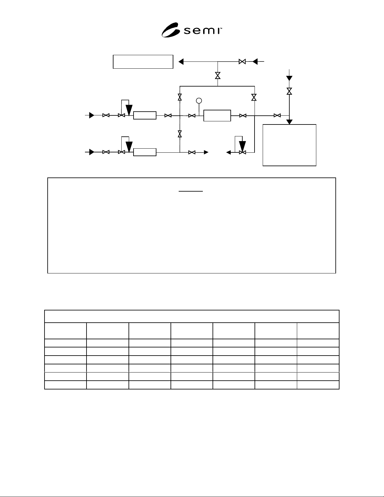
SEMI F68-1101 © SEMI 2001 6
Purge Gas
DUT
Pure Gas
(>9N Purity)
APIMS
or
Ultratrace
Analytical
Instrumentation
Impurity Analyzer
P1
Legend
DUT = Device Under Test
P1 = Test Pressure
R1 = Pure Gas 0–100 psig Regulator
R2 = Challenge Gas 0–100 psig Regulator
R3 = Vent Gas 0–100 psig Back Pressure Regulato
r
V1 = Pure Gas Source Isolation Valve
V2 = Pure Gas System Isolation Valve
V3 = Challenge Gas Source Isolation Valve
V4 = Challenge Gas System Isolation Valve
V5 = Challenge Gas Vent Isolation Valve
Challenge Gas
(~1% Impurity)
V4
V5
V6 V7
V8
V9
Vent
V10
V11
MFC1
R1
V1
V2
R3
V
6 = DUT Inlet Isolation Valve
V7 = DUT Outlet Isolation Valve
V8 = DUT Bypass Inlet Isolation Valve
V9 = DUT Bypass Outlet Isolation Valve
V10 = Impurity Analyzer Sample Isolation Valve
V11 = Impurity Analyzer Purge Gas Isolation Valve
V12 = APIMS/UAI Sample Isolation Valve
V13 = APIMS/UAI Purge Gas Isolation Valve
MFC1 = Pure Gas Mass Flow Controller
MFC2 = Challenge Gas Mass Flow Controller
V13
V12
MFC2
R2
V3
Figure 1
Suggested Point of Use Purifier Efficiency Test Setup
Table 1 Efficiency Of DUT Parameters
EFFICIENCY OF DUT
Impurity Pure Gas Flow Challenge Flow Inlet Conc Outlet Conc Zero Gas Analyzer
(slpm) (sccm) (ppm) (ppb) (ppb)
CH
4
H
2
O
2
N
2
CO
2
NMHC

SEMI F68-1101 © SEMI 20017
APPENDIX 1
MFC SIZING
NOTE: The material in this appendix is an official part of SEMI F68 and was approved by full letter ballot
procedures on August 27, 2001.
A1-1 To determine purifier efficiency, the
concentration of impurity entering the purifier and the
quantity of impurity downstream of the purifier must be
determined.
A1-2 Determine the manufacturer’s recommended
flow rate for the purifier. As an example, assume a
flow rate of 5 slpm.
A1-3 Determine the flow rate challenge gas required.
As an example, 5 sccm of a 1% challenge gas would be
blended into 4,995 sccm of pure gas to create at 10 ppm
test gas.
PPM 10
sccm 4,995sccm 5
sccm 5PPM 10,000
Gas Test =
+
×
=
As a large scale system, with a flow of 1,000 slpm, a
flow of 1 slpm of challenge gas (1% impurity) is
required to create a 10 ppm challenge.
PPM 10
slpm 999slpm 1
slpm 1PPM 10,000
Gas Test =
+
×
=
NOTICE: SEMI makes no warranties or
representations as to the suitability of the standard set
forth herein for any particular application. The
determination of the suitability of the standard is solely
the responsibility of the user. Users are cautioned to
refer to manufacturer’s instructions, product labels,
product data sheets, and other relevant literature
respecting any materials mentioned herein. These
standards are subject to change without notice.
The user’s attention is called to the possibility that
compliance with this standard may require use of copy-
righted material or of an invention covered by patent
rights. By publication of this standard, SEMI takes no
position respecting the validity of any patent rights or
copyrights asserted in connection with any item
mentioned in this standard. Users of this standard are
expressly advised that determination of any such patent
rights or copyrights, and the risk of infringement of
such rights, are entirely their own responsibility.
Copyright by SEMI® (Semiconductor Equipment and Materials
International), 3081 Zanker Road, San Jose, CA 95134. Reproduction o
f
the contents in whole or in part is forbidden without express written
consent of SEMI.

SEMI F69-0302 © SEMI 2002 1
SEMI F69-0302
TEST METHODS FOR TRANSPORT AND SHOCK TESTING OF GAS
DELIVERY SYSTEMS
This test method was technically approved by the Global Facilities Committee and is the direct responsibility
of the North American Facilities Committee. Current edition approved by the North American Regional
Standards Committee on November 27, 2001. Initially available at www.semi.org December 2001; to be
published March 2002.
1 Purpose
1.1 This document provides test methods for qualifying
the mechanical integrity of gas delivery systems
through vibration and shock testing.
2 Scope
2.1 The test methods recommended herein provide for
vibration (transport simulation) and shock testing of gas
delivery systems for semiconductor processing.
2.2 The test methods recommended herein apply to gas
delivery systems not crated or packaged for shipment.
Specifically, the test methods are to be applied to the
assembled and interconnected gas delivery components
and their associated mounting panel (back plane), with
or without a sheet metal enclosure.
2.3 For the purpose of this guideline, transportation
vibration, and its simulation, are expectedly more
severe than in-use vibrational levels. Thus the
transportation simulation test is considered acceptable
to assess mechanical integrity adequate for both
shipment and life-cycle vibrational stress of the gas
delivery systems.
2.4 The intent of the shock test is to provide further
assessment of equipment malfunction that may result
from shocks experienced during unpacking, installation,
or use in the field.
2.5 Successful completion of the tests recommended
herein is a recommended metric of mechanical integrity
for gas delivery systems architecture, design, and
assembly techniques.
2.6 This standard does not purport to address safety
issues, if any, associated with its use. It is the
responsibility of the user of this standard to establish
appropriate safety and health practices and determine
the applicability of regulatory limitations prior to use.
3 Limitations
3.1 This document, as a guide, does not provide
detailed information sufficient for conducting the tests.
It is the responsibility of the user and testing entity to
procure a copy of the referenced test procedures from
the issuing organization(s).
3.2 The test methods recommended herein are intended
to evaluate gas delivery systems architectures, design
principles, and assembly methodologies, not individual
production gas delivery systems.
3.3 The functional components of gas delivery
systems, for example mass flow controllers and
pressure transducers, may be adversely affected by the
forces seen during these tests. Such components may
require recalibration after testing.
4 Referenced Standards
NOTE 1: As listed or revised, all documents cited shall be
the latest publications of adopted standards.
4.1 SEMI Standards
SEMI F1 Specification for Leak Integrity of High-
Purity Gas Piping Systems and Components
4.2 Military Standards
1
MIL-STD-810 Environmental Engineering
Considerations and Laboratory Tests
5 Terminology
5.1 bag leak test A helium leak testing procedure in
which the system undergoing leak test is placed in a
helium-filled plastic bag while connected to a
functional helium leak detector.
5.2 g A unit of force equal to that exerted by gravity
upon a mass in equilibrium on the earth’s surface.
Expressed in Newtons (kg-m/sec.
2
).
5.3 leak tight Having a helium leak rate no greater
than that specified by the customer or end-user.
6 Vibration Testing
NOTE 2: Vibration testing should be performed in its entirety
before continuing to the shock testing.
6.1 In general, conduct vibrational testing according to
MIL-STD-810, Part Two, Laboratory Test Method
514.5, Procedure 1, Category 4, for 3 hours in each axis
(a total of 9 hours). This will subject the gas delivery
1 DODSSP, Building 4 / Section D, 700 Robbins Avenue,
Philadelphia, PA 19111-5094