semi合集-English.pdf - 第526页
SEMI E76-0299 SEMI 1998, 1999 6 Figure 1 Template Example Figure 2 Jig Ex ample

SEMI E76-0299
SEMI 1998, 1999
5
should be consistent with those defined in the Facilities
Interface Specification and should not deviate from
equipment to equipment of a specific model and
revision. EPOC tolerances need to be +/- 6.35 mm (+/-
1/4 inch) in all directions as measured from the supplier
defined equipment datum point. Tighter tolerances
should be considered for inflexible or difficult to move
hookups such as large diameter (over 2 inch) exhaust or
water lines. Connector sizes and types should match
exactly.
6.3.2 Table 2 - EPOC Consistency Recommendations
identify equipment variations and levels of consistency
required for equipment points of connection location,
connector type and size.
6.3.3 In Table 2, the term “Should Match” identifies
areas that have traditionally been the most costly and
where significant gains can be made in achieving
installation efficiency . The term “Could Match”
identifies areas where modest gains can be made in
installation efficiency .
6.4 Equipment Point of Connection Reduction
6.4.1 The number of connection points to the
equipment should be kept to a minimum. The EPOC’s
located on wafer processing equipment should follow a
strategy commonly referred to as single line drops,
where there is only one point of connection per service
per piece of equipment. Where feasible, distribution of
a particular facility (e.g., chilled water, waste drains for
the same type of chemicals) should be distributed
through internal manifolding. Internal equipment
manifolding should be configured to allow for
configurable equipment sub-systems like process
chambers and gas panels. In addition to manifolding, all
other interface box functions should be configured on-
board the equipment this includes any required shut-off
valves, regulators, filters, QC sample valves and
pressure indicators.
6.5 Equipment Point of Connection Interface Panel
6.5.1 Once EPOC locations and groupings have been
defined and standardized for purposes of consistency,
the supplier could utilize an interface panel concept for
simplifying equipment hook-up. The interface panel
should consist of a physical panel that becomes part of
the permanent equipment installation. All EPOC’s
should be comprehended in the layout of the interface
panel using the recommendations for location,
grouping, and consistency as discussed in Sections 6.1,
6.2, and 6.3. The supplier should design a standard
interface panel layout that supports a given equipment
type and all associated revisions.
6.5.2 Common connector technologies, types, and
sizes should be utilized along with provisions for
containment of hazardous materials. Typically,
hazardous production material connections are
contained within the equipment
6.5.3 Spacing of multiple gas and liquid connections
on the interface panel should provide sufficient access
and spacing for installation and maintenance for
multiple lines (i.e., orbital weld head, wrench, and test
fittings).
7 Pre-facilitation Recommendations
7.1 The pre-facilitation strategy should provide the
device manufacturer with the ability to efficiently and
accurately install UPOC’s prior to equipment delivery,
allowing immediate hook-up of the equipment upon
arrival to the fab. The equipment supplier should
provide a template and/or jig, as well as a EPOC
interface panel (if applicable) or pre-facilitation
pedestal prior to the equipment delivery as part of a
strategy to support accurate pre-facilitation of utility
points of connection. In situations where a pedestal is
being utilized (see Section 7.4), the pedestal can serve
as an aide to pre-facilitation. The supplier and device
manufacturer should discuss and agree on the chosen
strategy.
7.2 Templates: The template provides a two-
dimensional guide that projects EPOC locations to a
two-dimensional surface, typically the floor. This would
allow the device manufacturer to open popouts, core
holes, etc., and pre-facilitate to a point close to, but not
necessarily including, the UPOC. See Figure 1 for a
representative example of a Template.
7.3 Jigs: The jig provides a guide that locates the -
EPOC’s in three-dimensional space. This would allow
the device manufacturer to pre-facilitate to the UPOC’s
or at least prefabricate the facility lines and UPOC’s
such that final hookup could be accomplished
immediately after setting the equipment. See Figure 2
for a representative example of a Jig.
7.4 Pre-facilitation Pedestal: Application notes and
three representative examples of using pedestals to
support pre-facilitation are included in the related
information section at the end of this document.
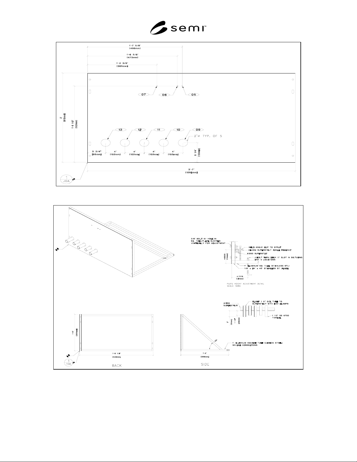
SEMI E76-0299
SEMI 1998, 1999
6
Figure 1
Template Example
Figure 2
Jig Example

SEMI E76-0299
SEMI 1998, 1999
7
8 Documentation Recommendations
8.1 Equipment suppliers should provide the following
documentation concerning equipment point of
connections and/or template, jig, and pre-facilitation
pedestal to the device manufacturers. The device
manufacturer should provide to the supplier, the dates
the documentation is required if it is not already
specified in this guide.
a) All documentation should be supplied prior to
the equipment delivery to the device
manufacturer (as deemed appropriate by both
the device manufacturer and supplier) and
includes a minimum of two sets per piece of
equipment .
b) Text and step-by-step procedures should be
written in a concise, coherent manner enabling
the device manufacturers to achieve and
sustain all system performance goals.
c) All drawing documentation provided
electronically should be in a format which is
compatible with standard computer aided
design (CAD) software used by device
manufacturers. The CAD format should be
compatible with common CAD systems, to
include but not limited to, .DWG, .DXF,
.DXB, .PS, and .WMF file extensions.
d) The documentation should match the revision
of the equipment delivered.
8.2 The equipment supplier should notify the device
manufacturer within 30 days of any equipment
configuration changes which have an impact on the
facility or installation requirements. These changes
include, but are not limited to, equipment dimensions,
equipment elevation, and equipment points of
connection. There should be no changes made within 3
weeks of equipment shipment.
8.3 EPOC Documentation
8.3.1 Equipment requirements for utilities and
installation should be provided by the equipment
supplier. Included EPOC documentation should contain
but not be limited to the following information.
a) Floor space requirements (footprint).
b) EPOC matrix indicating service, size/type of
connection, location plane, and x,y,z
dimensions relative to equipment datum point.
c) Two dimensional drawings showing the
equipment points of connection that specify the
protrusion depths.
8.3.2 For interface panels, the equipment supplier
should provide documentation that includes clear
instruction for assembly and positioning the interface
panel, a key that clearly identifies which EPOC’s are
included, and appropriate design drawings such that the
device manufacturer can include the interface panel in
their respective construction designs.
8.3.3 The following documentation is also required to
support the equipment installation activity but is not
directly related to the EPOC.
a) Equipment elevation drawings representing all
sides of the equipment.
b) Air conditioning and ventilation requirements
(acceptable temperature and humidity ranges,
exhaust plumbing, etc.).
c) Vibration requirements (acceptable amplitude
and frequency).
d) Electrical requirements (voltage, current,
wattage, number of phases, power quality,
supply voltage wave form requirements, etc.).
e) Vacuum amounts, gases (grade and flow),
chilled water flow and other environmental
requirements including plumbing requirements
(type, size, etc.) for each.
f) A section detailing the procedures to be
followed during equipment unpacking and
inspection.
g) A section detailing step-by-step set-up
procedures that will specifically outline
machine assembly and installation on the
factory floor.
8.4 Template, Jig, or Pre-facilitation Pedestal
Documentation.
8.4.1 For templates, jigs, and pre-facilitation pedestals,
the equipment supplier should provide documentation
that includes clear instruction for assembly, clear
instruction for aligning the template, jig, or pre-
facilitation pedestal relative to the equipment datum
point, and a key that clearly identifies which EPOC’s
are included. The documentation should also clearly
indicate which pieces of equipment (model and revision
number) that are supported by a specific template, jig,
or pre-facilitation pedestal.
8.4.2 For pre-facilitation pedestals, the equipment
supplier should also provide appropriate design
drawings and information such that the device
manufacturer can include the pedestal design in their
respective construction designs. In addition, the supplier
should provide applicable documentation required for
structural certification.