semi合集-English.pdf - 第3199页
SEMI E126-0305 © SEMI 2003, 2005 8 … #1 Text in italics provides f u rther description o f a field; it is not part of the template. Form at descriptors for EQIPs repres ent union of requir ed descriptors for supported EQ…
SEMI E126-0305 © SEMI 2003, 2005 7
9.5.5 Listing of Supported Linked Process Program Parameters — This field is a listing of supported PPPs as
indicated in the corresponding “EQIP and Linked PPP Support Compliance Sheet” (see ¶9.5.1.3).
9.5.6 Linked PPP Format Descriptors — These fields collectively provide the description of the format of the
supported EQIPs. Note that required descriptor fields are Name, Data Type, and Data Units. Additional descriptor
fields can be provided as desired.
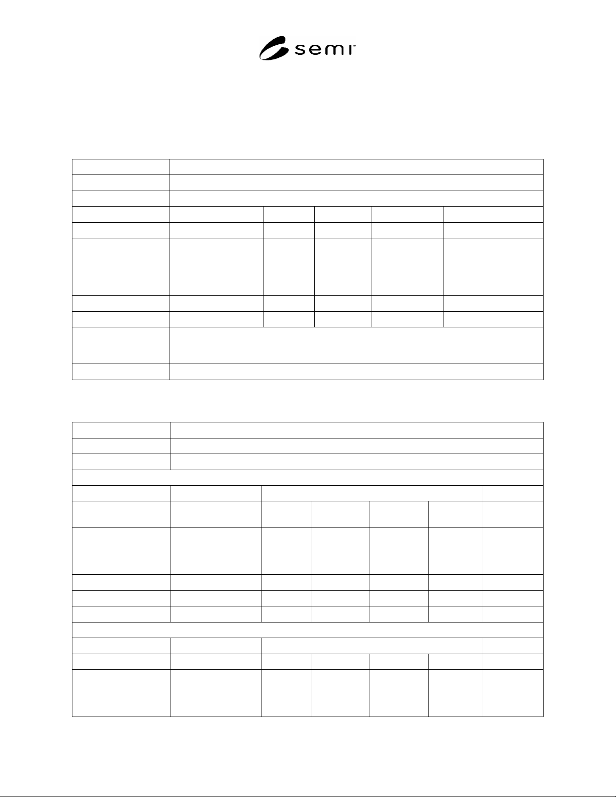
Table 4 EQIP and Linked PPP Support Compliance Sheet Template
Company
Company Name
Unique Identifier
Key for Identifying Classification of Equipment Within Company (e.g., Model Number(s))
Equipment Type(s)
Types from Figure 2; minimum of one type must be specified
EQIP Required Supported Linked PPPs Comments
From Table 2, linked to
Equipment Type
From Table
2
Y/N Could include
recommended method for
measuring and/or
calculating EQIP
parameter
…
Supported Methods for
Individual Actuation of
Linked PPPs
Additional Information
Additional Information, See ¶9.5.1.5
#1
Text in italics provides further description of a field; it is not part of the template.
Table 5 EQIP and Linked PPP Data Format Compliance Sheet Template
Company
Company Name
Unique Identifier
Key for Identifying Classification of Equipment Within Company (e.g., Model Number(s))
Equipment Type (s)
From list in Table 1
EQIP DATA FORMATS
Format Descriptors
EQIP From
Table 3
From Table 3 From Table 3 . . . Comments
Supported EQIPs (from
EQIP and Linked PPP
Support Compliance
Sheet)
Could
include
additional
descriptors
…
LINKED PPP DATA FORMATS
Format Descriptors
Linked PPP Name Data Type Data Units … Comments
Supported Linked PPPs
(from EQIP and Linked
PPP Support
Compliance Sheet)
Could
include
additional
descriptors

SEMI E126-0305 © SEMI 2003, 2005 8
…
#1
Text in italics provides further description of a field; it is not part of the template. Format descriptors for EQIPs represent union of required
descriptors for supported EQIPs. Format descriptor fields for an EQIP do not have to be filled out if the entity claiming compliance and
submitting the compliance sheets does not provide a measurement of the EQIP (e.g., the EQIP for the process tool is measured by another
metrology tool). A value of “N.A.” indicating “not applicable” is inserted wherever the descriptor is not specified and is not supported for an
EQIP.
10 Template for Adding Equipment Types and EQIPs to this Standard
10.1 The standard is structured so that it can be updated. Specifically, EQIPs for equipment types may be added to
an existing set, as the community reaches consensus on these additions. Further, EQIPs may be defined for a new
equipment type not previously addressed in this standard. Thus typical additions to this standard will impact Table 2
and Table 3, and possibly Table 1 of this standard. These typical additions should not impact any other portions of
this standard.
10.2 Template — The template for typical additions to this standard is shown in Table 6. Note that this template
addresses only the technical content of the ballot addition to the standard. For development and submission of the
complete ballot, refer to SEMI documentation.
Table 6 Template for Typical Additions to this Standard
# Ballot Component Conditions for including in Ballot
1 Add the following rows to Table 1 Include only if adding equipment types. Add one row for each type added.
2 Add the following EQIP information
to the EQIP column of Table 2
Include only if adding EQIPs to existing equipment types. Add for each new
EQIP defined. Add to each equipment type that will use this EQIP. Indicate
requirement (Y/N). Note that one of ballot components 2 and 3 must be in
included in the ballot.
3 Add the following rows to Table 2 Include only if adding equipment types. Define the EQIPs for these new types.
Note that one of ballot components 2 and 3 must be in included in the ballot.
4 Add the following rows to Table 3 This component must be included in the ballot. Add a row for each new EQIP
defined.
#1
Column 1 is an index column utilized only for reference.
NOTICE: SEMI makes no warranties or representations as to the suitability of the standards set forth herein for any
particular application. The determination of the suitability of the standard is solely the responsibility of the user.
Users are cautioned to refer to manufacturer's instructions, product labels, product data sheets, and other relevant
literature, respecting any materials or equipment mentioned herein. These standards are subject to change without
notice.
By publication of this standard, Semiconductor Equipment and Materials International (SEMI) takes no position
respecting the validity of any patent rights or copyrights asserted in connection with any items mentioned in this
standard. Users of this standard are expressly advised that determination of any such patent rights or copyrights, and
the risk of infringement of such rights are entirely their own responsibility.
Copyright by SEMI® (Semiconductor Equipment and Materials
International), 3081 Zanker Road, San Jose, CA 95134. Reproduction of
the contents in whole or in part is forbidden without express written
consent of SEMI.

SEMI E127-0705 © SEMI 2003, 2005 1
SEMI E127-0705
SPECIFICATION FOR INTEGRATED MEASUREMENT MODULE
COMMUNICATIONS: CONCEPTS, BEHAVIOR, AND SERVICES (IMMC)
This specification was technically approved by the global Information & Control Committee. This edition
was approved for publication by the global Audits and Reviews Subcommittee on April 7, 2005. It was
available at www.semi.org in June 2005 and on CD-ROM in July 2005. Originally published July 2003;
previously published November 2004.
Contents
1 Purpose.......................................................................................................................................................................4
1.1 Integrated Measurement......................................................................................................................................4
1.2 Specification for the Integrated Measurement Module Communications (IMMC)..............................................4
2 Scope ..........................................................................................................................................................................4
2.1 Scope of This Document ......................................................................................................................................4
3 Limitations..................................................................................................................................................................4
3.1 Host/Integrated Equipment Interface ..................................................................................................................4
3.2 Object-Based Implementation..............................................................................................................................4
3.3 In-Situ Processing................................................................................................................................................4
4 Referenced Standards and Documents .......................................................................................................................4
4.1 SEMI Standards...................................................................................................................................................4
4.2 Other Sources ......................................................................................................................................................5
5 Terminology ...............................................................................................................................................................5
5.1 Abbreviations and Acronyms...............................................................................................................................5
5.2 Definitions ...........................................................................................................................................................5
6 Conventions................................................................................................................................................................6
6.1 Object Conventions..............................................................................................................................................6
6.2 State Model Conventions.....................................................................................................................................7
6.3 Service Message Representation .........................................................................................................................7
7 General Requirements ................................................................................................................................................8
7.1 Protocol Requirements ........................................................................................................................................8
7.2 Required Standards .............................................................................................................................................8
7.3 Required Basic Capabilities ................................................................................................................................8
7.4 State Models ........................................................................................................................................................9
7.5 Objects.................................................................................................................................................................9
7.6 Service Requirements.........................................................................................................................................10
8 Overview ..................................................................................................................................................................10
8.1 Background........................................................................................................................................................10
9 Communication Ports and Clients ............................................................................................................................10
9.1 Ports ..................................................................................................................................................................10
9.2 Clients................................................................................................................................................................10
9.3 Bandwidth and Performance .............................................................................................................................11
10 Integrated Measurement Module Object Model .....................................................................................................11
10.1 Description ......................................................................................................................................................11
11 The Integrated Measurement Module Object .........................................................................................................12
11.1 Relationship of IMM Object And Physical Module .........................................................................................12
11.2 IMM Service State Model ................................................................................................................................12
11.3 Object Attributes..............................................................................................................................................13
11.4 System Initialization.........................................................................................................................................15
11.5 IMM Events and Alarms..................................................................................................................................16
11.6 IMM Object Services .......................................................................................................................................17
12 Substrate Transfer Path Object ...............................................................................................................................18
12.1 Description ......................................................................................................................................................18
12.2 Object State Model ..........................................................................................................................................18
12.3 Object Attributes..............................................................................................................................................20