semi合集-English.pdf - 第186页
SEMI E23-1104 © SEMI 1991, 2004 4 Table 3 Signals for the Photo-Co upled Parallel I/O Interface Signal Type P/A D escription VALID A->P This signal remains high (ON) while the data of CS_0, CS_1, CS _2 is effective. (…
SEMI E23-1104 © SEMI 1991, 2004 3
5 Parallel I/O Interface Specification
5.1 This standard refers only to the cassette transfer between active and passive equipment.
5.2 Wire-Connected Parallel I/O Interface Specification — The equipment is to have a parallel I/O interface for the
passive mode when it becomes passive, and the parallel I/O interface for the active mode when it becomes active.
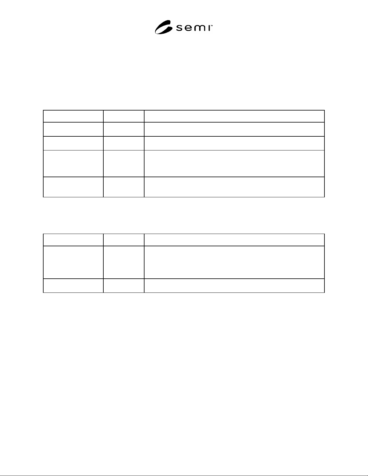
5.2.1 Signals for Each Cassette Stage — The cassette stage is to have the input/output signal lines listed in Table 1.
Table 1 Signals for Each Cassette Stage (Wire-Connected Interface)
Signal Type P/A Description
L_REQ (LOAD
REQUEST)
P->A This signal means that the CS can be loaded. The signal turns OFF when the
cassette is detected on the CS. (The CS is a cassette stage.)
U_REQ (UNLOAD
REQUEST)
P->A This signal means that the CS can be unloaded. The signal turns OFF when it is
detected that the cassette has been removed from the CS.
READY P->A This signal means that the CS is in a state where it can be accessed by the active
equipment. It turns ON when the CS is in the READY state after the TR_REQ
signal from the active turns ON. The signal turns OFF by handshakes with the
COMPT signal.
TR_REQ (TRANSFER
REQUEST)
A->P This signal turns ON when the active equipment is going to start transferring the
cassette. It turns OFF when the BUSY signal is OFF. (Active equipment starts
transferring the cassette with the BUSY ON after recognizing the READY ON.)
5.2.2 Common Signals — The signals in Table 2 show the status of the cassette transfer action of the active
equipment. The CS’s are allowed to input these signals commonly from active equipment.
Table 2 Common Signals (Wire-Connected Interface)
Signal Type P/A Description
BUSY A->P This signal turns ON when the active equipment starts transferring the cassette to
the CS while it is in READY and turns OFF after the robot has loaded or unloaded
a cassette and has moved away from the interactive zone. The passive equipment
does not perform any mechanical action in the interactive zone while this signal is
ON.
COMPT (COMPLETE) A->P This signal means the active equipment has completed the transfer action. It turns
OFF after handshaking with the READY signal.
NOTE 1: It is recommended that the BUSY signal turn OFF after the active equipment has confirmed L_REQ (or U_REQ) is
OFF.
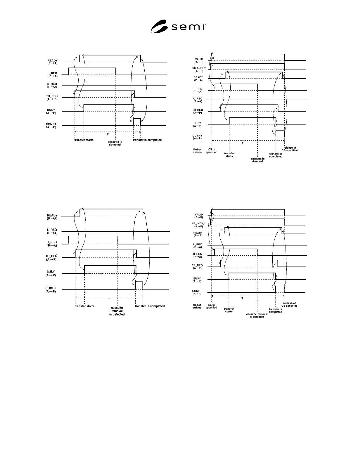
5.2.3 Cassette Transfer Sequence — Time charts for the cassette transfer sequence are shown in Figures 3 (a) and
(b).
5.2.3.1 The TR_REQ from the active equipment initiates the cassette transfer sequence. The active equipment starts
carrying out the transfer action with the BUSY ON as soon as it recognizes that the READY signal of the passive
equipment is ON. The handshake is finished after the cassette transfer action has been completed.
5.3 Photo-Coupled Parallel I/O Interface Specification — This interface is concerned only with the cassette transfer
between the process equipment and the transport robot vehicle. The robot vehicle is active and the process
equipment is passive.
5.3.1 This interface is defined between the robot and the cassette stages to which the robot can transfer a cassette at
the same stopping position.
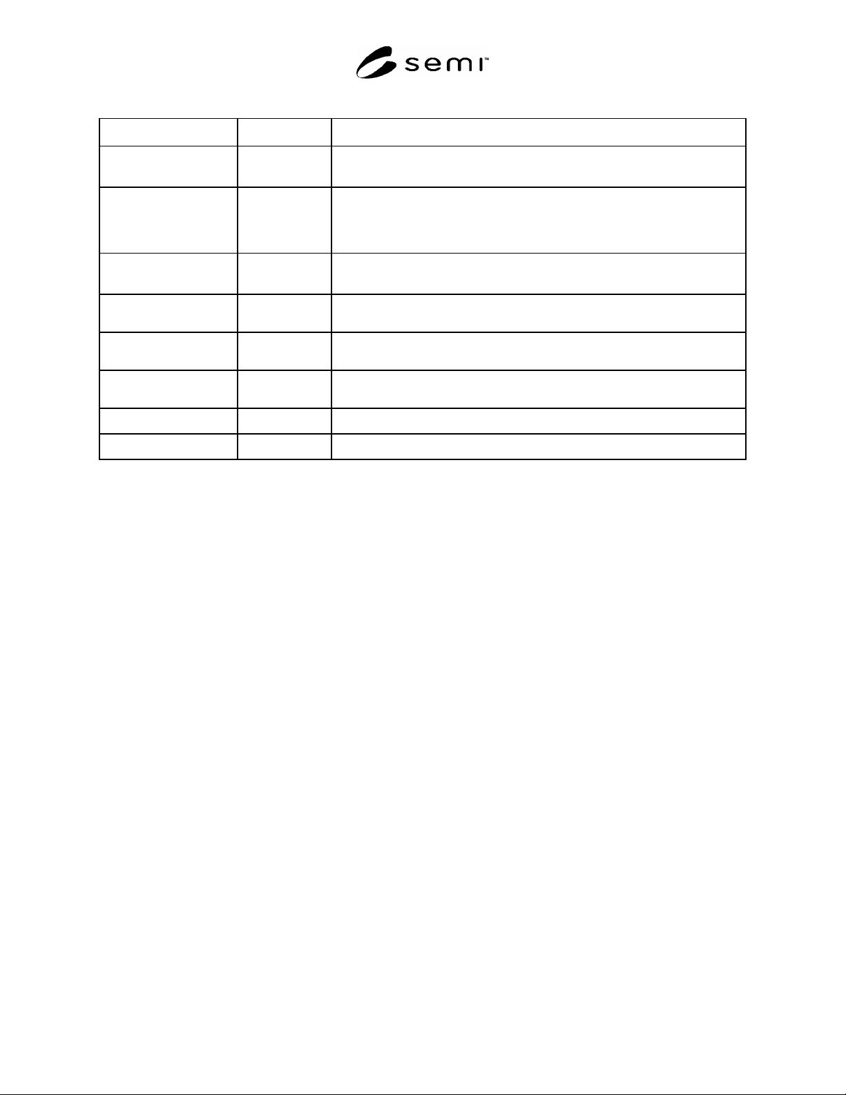
5.3.2 Signals — The signals for the photo-coupled parallel I/O interface are listed in Table 3. The CS_0, CS_1, and
CS_2 signals specifying the CS to or from which the active equipment transfers and the VALID signal indicating
effectiveness of the data of CS_0~CS_2, are newly added to the signals defined in the wire-connected parallel I/O
interface.
SEMI E23-1104 © SEMI 1991, 2004 4
Table 3 Signals for the Photo-Coupled Parallel I/O Interface
Signal Type P/A
D
escription
VALID A->P This signal remains high (ON) while the data of CS_0, CS_1, CS_2 is effective.
(The data of CS_0, CS_1, CS_2 is not effective when VALID signal is OFF.)
CS_0 (LSB) CS_1 CS_2
(MSB)
A->P The 3-bit signals specify the cassette stage number (0 ~ 7) of the passive equip-
ment, to or from which the active equipment (robot vehicle) is going to transfer a
cassette. They are set before the VALID signal turns ON. VALID and
CS_0~CS_2 signal.
TR_REQ A->P This is the same in the wire-connected parallel I/O specification and is valid for
the specified CS.
L_REQ P->A This is the same in the wire-connected parallel I/O specification and is valid for
the specified CS.
U_REQ P->A This is the same in the wire-connected parallel I/O specification and is valid for
the specified CS.
READY P->A This is the same in the wire-connected parallel I/O specification and is valid for
the specified CS.
BUSY A->P This is the same in the wire-connected parallel I/O specification.
COMPT A->P This is the same in the wire-connected parallel I/O specification.
5.3.3 Cassette Transfer Sequence — Time charts for the cassette transfer sequence in the case of the photo-coupled
interface are shown in Figure 4 (a) and (b). After the active equipment (robot vehicle) reaches the process
equipment, it sets the CS_0, CS_1, CS_2 3-bit-signals to specify the CS number of the passive equipment, to or
from which the active equipment (robot vehicle) is going to transfer a cassette. Then the robot vehicle turns the
VALID signal ON, which shows the date of the CS_0, CS_1, CS_2 signal is effective. After the cassette stage is
specified, cassette transfer sequence is the same as in the wire-connected parallel I/O specification. TR_REQ,
L_REQ,U_REQ, READY signals show the data for the specified CS while the VALID signal is ON, and the CS_0,
CS_1, CS_2 signals are inhibited to change their data while the VALID signal is ON.
5.4 Error Detection and Recovery — The cassette transfer using this interface in the practical manufacturing lines
will need handshake time interval control, cassette misalignment detection, and report of alarm or error to find an
error or abnormal termination in the cassette transfer. An error recovery procedure with appropriate assist by human
operators will be also required. This standard, however, does not define the specifications related to the error
detection and recovery because of difference in process time, failure mode, and error recovery procedure of
individual equipment and system.
5.4.1 The recommendation for basic error detection is that the active equipment should control handshake time
intervals, and at least the interval time T between the beginning of the cassette transfer and the end of the transfer
should be controlled — see the time chart of the cassette transfer sequence shown in Figures 3(a), 3(b), 4(a), and
4(b), describing the time chart of the cassette transfer sequence.
SEMI E23-1104 © SEMI 1991, 2004 5
Figure 3A
Cassette Load Sequence
(Wire-Connected Interface)
Figure 3B
Cassette Unload Sequence
(Wire-Connected Interface)
Figure 4A
Cassette Load Sequence
(Photo-Coupled Interface)
Figure 4B
Cassette Load Sequence
(Photo-Coupled Interface)