semi合集-English.pdf - 第6890页
SEMI S5-0703 © SEMI 1993, 2003 5 F i gu r e 1 N i trogen Flow R a te 0 200 400 600 800 1000 1200 1400 1600 1800 2000 700 2100 7000 14000 21000 Cylin der Pressure (kPa) Nitrogen Flow Rate (slm) 0.15 lo 0.15 hi 0.25 lo 0.2…
SEMI S5-0703 © SEMI 1993, 2003 4
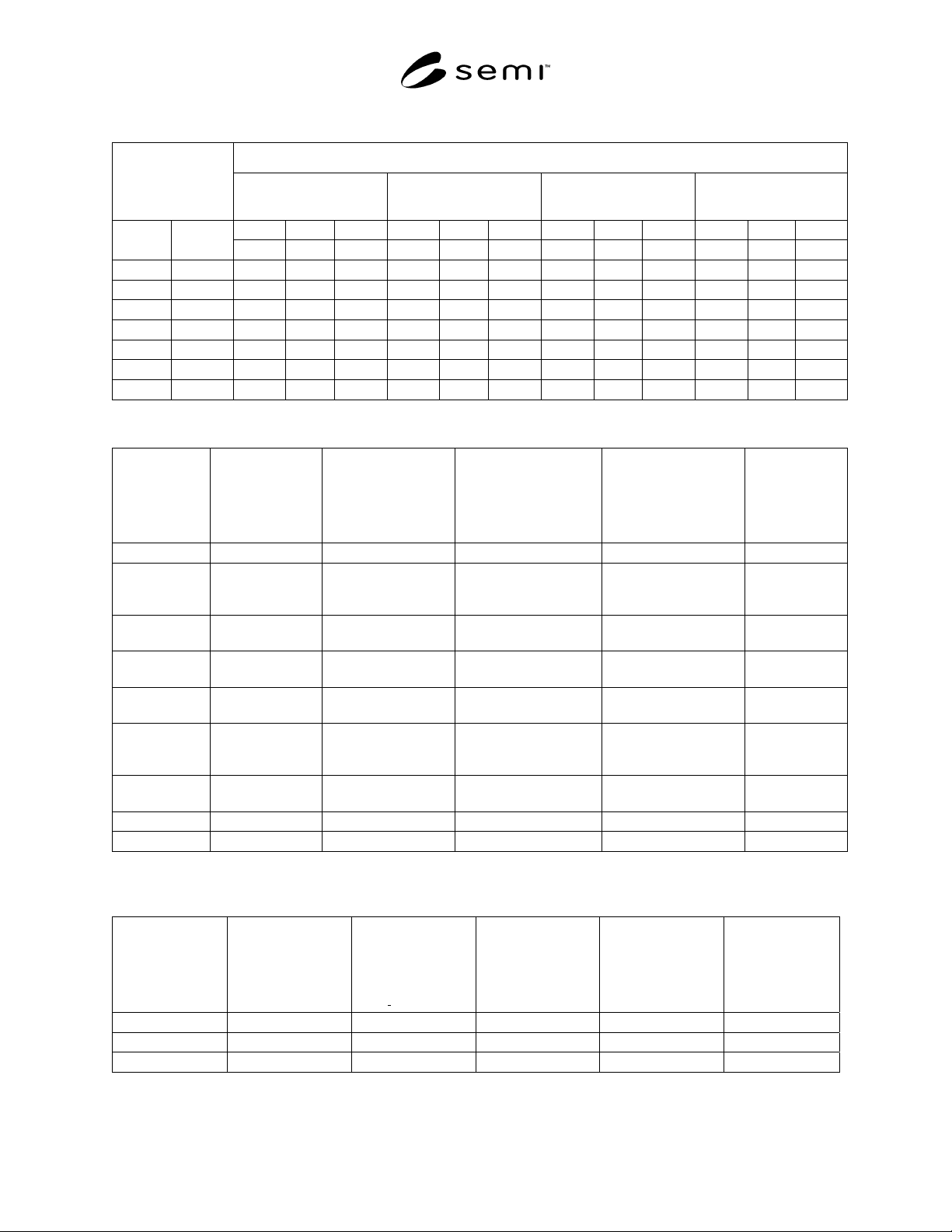
Table 1 Critical Nitrogen Flow Rates (Q
NT
) For Flow Limiting Devices
Critical Flow Rate (slm) of nitrogen at the following cylinder pressures:
Equivalent Orifice
Size
700 kPa gauge
(102 psig)
2100 kPa gauge
(305 psig)
7000 kPa gauge
(1015 psig)
21000 kPa gauge
(3045 psig)
min. nom. max. min. nom. max. min. nom. max. min. nom. max.
mm inch
−20% +20% −20% +20% −20% +20% −20% +20%
0.15 0.006
1.04
1.31
1.57 2.86
3.57
4.29 9.21
11.5
13.8 27.4
34.2
41.0
0.25 0.01
2.90
3.62
4.35 7.94
9.93
11.9 25.6
31.0
38.4 76.0
95.0
114
0.50 0.02
11.6
14.5
17.4 31.8
39.7
47.7 102
128
153 304
380
456
0.75 0.03
26.1
32.6
39.1 71.5
89.4
107 230
288
345 684
855
1026
1.00 0.04
46.4
58.0
69.6 127
159
191 409
512
614 1216
1520
1824
1.25 0.05
72.5
90.6
108 199
248
298 640
799
959 1900
2375
2850
1.50 0.06
104
130
157 286
357
429 921
1151
1381 2736
3421
4105
Table 2 Hazardous Gases for Which Flow Limiting Devices May be Used
Hazardous
Gas Type
Standard
Density (D), 1
atm., 0°C
[kg/m
3
(lbs/ft
3
)]
Cylinder Pressure
(P
cyl
) Typical Max.
@ Room Temp.
[kPa_gauge (psig)]
(See Note 1.)
Compressibility
Factor (Z) @ Typ.
Max.Cylinder
Pressure (See Note 2.)
Compressibility
Factor (z) @ 10%
Typ. Max.Cylinder
Pressure (See Note 2.)
Max. Flow
Rate (q) 0.25
mm (0.01 in.)
Equiv.Orifice
(slm)
Arsine, AsH3 3.45 (0.216) 1,410 (205) 0.81 0.98 5.5
Carbon
Monoxide,
CO
1.250 (0.078) 11,385 (1,650) 0.97 1.0 63
Diborane,
B2H6
1.250 (0.078) 1% in N2 12,410
(1,800)
0.29 @ 7,000 (1,015) 0.93 @ 700 (103) 1% in N2 68
Germane,
GeH4
3.415 (0.213) 607 (88) 0.94 0.99 2.4
Hydrogen,
H2
.090 (0.0056) 15,180 (2,200) 1.03 1.0 303
Nitrogen
Trifluoride,
NF3
3.200 (0.199) 10,000 (1,450) 0.64 0.96 43
Phosphine,
PH3
1.519 (0.095) 4,095 (594) 0.52 0.95 29
Silane, SiH4 1.433 (0.090) 8,280 (1,200) 0.36 0.94 70
Stibine, SbH3 1.444 (0.090) --- --- --- ---
NOTE 1: Cylinder pressures will vary, consult gas supplier to verify the actual cylinder pressure.
NOTE 2: Compressibility factors are interpolated from available data, consult gas supplier for alternate pressures.
Table 3 Mixing Gases
Mixing Gas Type
Standard Density
(D), 1 atm., 0°C
[kg/m
3
(lbs/ft
3
)]
Cylinder
Pressure* (P
cyl
)
Typical Max. @
Room Temp
[kPa
gauge (psig)]
Compressibility
Factor (Z) @ Typ.
Max. Cylinder
Pressure
Compressibility
Factor (Z) @ 10%
Typ. Max.Cylinder
Pressure
Max. Flow Rate
(Q) thru 0.25 mm
(0.01 in.)
Equivalent Orifice
(slm)
Argon, Ar 1.788 (0.111) 17,180 (2,490) 0.93 0.99 81
Helium, He 0.179 (0.011) 17,180 (2,490) 1.1 1.0 235
Nitrogen, N
2
1.250 (0.078) 17,180 (2,490) 1.0 1.0 93
SEMI S5-0703 © SEMI 1993, 2003 5
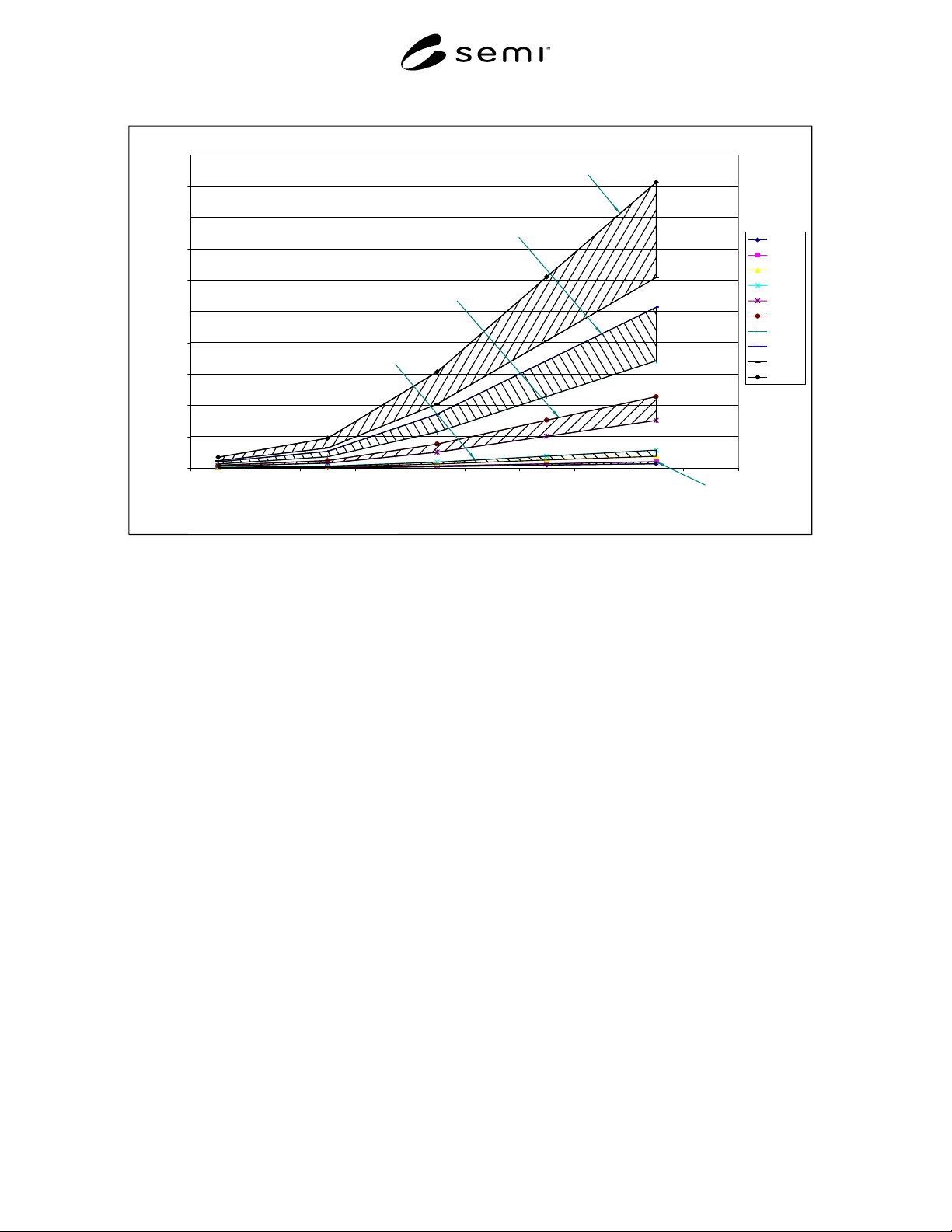
Figure 1 Nitrogen Flow Rate
0
200
400
600
800
1000
1200
1400
1600
1800
2000
700 2100 7000 14000 21000
Cylinder Pressure (kPa)
Nitrogen Flow Rate (slm)
0.15 lo
0.15 hi
0.25 lo
0.25 hi
0.50 lo
0.50 hi
0.75 lo
0.75 hi
1.00 lo
1.00 hi
1.00 mm equiv. orifice
0.75 mm equiv. orifice
0.50 mm equiv. orifice
0.25 mm equiv. orifice
0.15 mm equiv. orifice
Figure 1
Nitrogen Flow Rate
NOTICE: SEMI makes no warranties or representations as to the suitability of the standards set forth herein for any
particular application. The determination of the suitability of the standard is solely the responsibility of the user.
Users are cautioned to refer to manufacture's instructions, product labels, product data sheets, and other relevant
literature, respecting any materials or equipment mentioned herein. These standards are subject to change without
notice.
The user’s attention is called to the possibility that compliance with this standard may require use of copyrighted
material or of an invention covered by patent rights. By publication of this standard, SEMI takes no position
respecting the validity of any patent rights or copyrights asserted in connection with any item mentioned in this
standard. Users of this standard are expressly advised that determination of any such patent rights or copyrights, and
the risk of infringement of such rights, is entirely their own responsibility.
Copyright by SEMI® (Semiconductor Equipment and Materials
International), 3081 Zanker Road, San Jose, CA 95134. Reproduction o
f
the contents in whole or in part is forbidden without express written
consent of SEMI.

SEMI S6-93 © SEMI 19931
SEMI S6-93
SAFETY GUIDELINE FOR VENTILATION
NOTICE: This guideline does not purport to address
all of the safety issues associated with its use. It is the
responsibility of the user of this guideline to establish
appropriate safety and health practices and determine
the applicability of regulatory limitations prior to use.
NOTE: As listed or revised, all documents cited shall be the
latest publications of adopted standards.
1 Introduction
The equipment supplier should design an internal
equipment exhaust system that is efficient when
connected to potential users’ exhaust systems. Seldom,
if ever, are users’ systems designed for a specific piece
of process equipment or set of process equipment. Most
users’ exhaust systems are designed and installed to
industry-accepted exhaust principles.
2 Purpose
This document is intended to help the semiconductor
equipment supplier design equipment exhaust systems
to a common set of performance criteria as well as to
provide assistance to both users and suppliers in the
understanding of exhaust requirements for equipment
systems. It is not intended to establish design
specifications. The supplier will still own, and be
responsible for, the information it specifies. This
guideline has six concurrent performance-related
objectives.
2.1 Ensure hazardous gases, fumes, and vapors are
controlled (during normal operations of equipment and
facilities services) such that concentrations present in
the work room air should be less than 1.0% of the
Threshold Limit Value (TLV), as established by the
American Conference of Governmental Industrial
Hygienists (ACGIH) or Permissible Exposure Limit
(PEL) as published by the appropriate regulatory
agency, whichever is lower.
2.2 Ensure exhaust is provided within specifications to
support the proper operation of equipment.
2.3 Optimize the user’s exhaust system(s).
2.4 Use the most cost effective methods to interface
with user’s exhaust systems.
2.5 Provide a platform for communicating “special
case” exhaust requirements.
2.6 Establish guidelines for measurement and
communication of equipment exhaust requirements.
3 Scope
This guideline applies to all semiconductor equipment
that incorporates exhausted enclosures that are intended
to be connected to user facilities’ exhaust system(s).
This document is written with the assumption that the
users’ exhaust distribution systems will be designed
with central fans, ducting, and, where applicable,
abatement equipment. Where users use other types of
exhaust systems, equipment suppliers should acquire
exhaust specifications from the users. Whether
equipment is connected to a central exhaust system or
to one which serves only that piece of equipment, this
guideline should be applied.
4 Referenced Documents (s ee Appendix 2)
5 Terminology
5.1 balancing — Adjustments made after the
ventilated equipment and the ventilation system are
installed to assure that airflow to each piece of
ventilated equipment is within design specifications.
5.2 capture — To entrain undesirable elements (gases,
fumes, vapor, and particles) in the exhaust stream for
removal.
5.3 dilute — To reduce the concentration of
undesirable elements to acceptable levels. Dilution is a
function of flow volume.
5.4 flow velocity (V) — The average speed at which
the effluent stream travels through the exhaust duct. It
is measured in meters per second (m/s) or feet per
minute (fpm).
5.5 flow volume (Q) — The volumetric flow rate of
the effluent stream passing a given location in the
exhaust system per unit of time. It is measured in cubic
meters per second (m
3
/s) or cubic feet per minute (cfm).
5.6 initiate motion — To use an exhaust stream to start
contaminants (or machine parts) moving from a rest
position.
5.7 long radius elbow — An exhaust duct elbow that
has a center line radius 1.5 or more times the duct
diameter.
5.8 set point tolerance — The range (+/-) of static
pressure within which an exhaust enclosure will
perform efficiently and effectively.
5.9 static pressure (SP) — The measure of differential
pressure across the duct wall to the ambient pressure