semi合集-English.pdf - 第29页
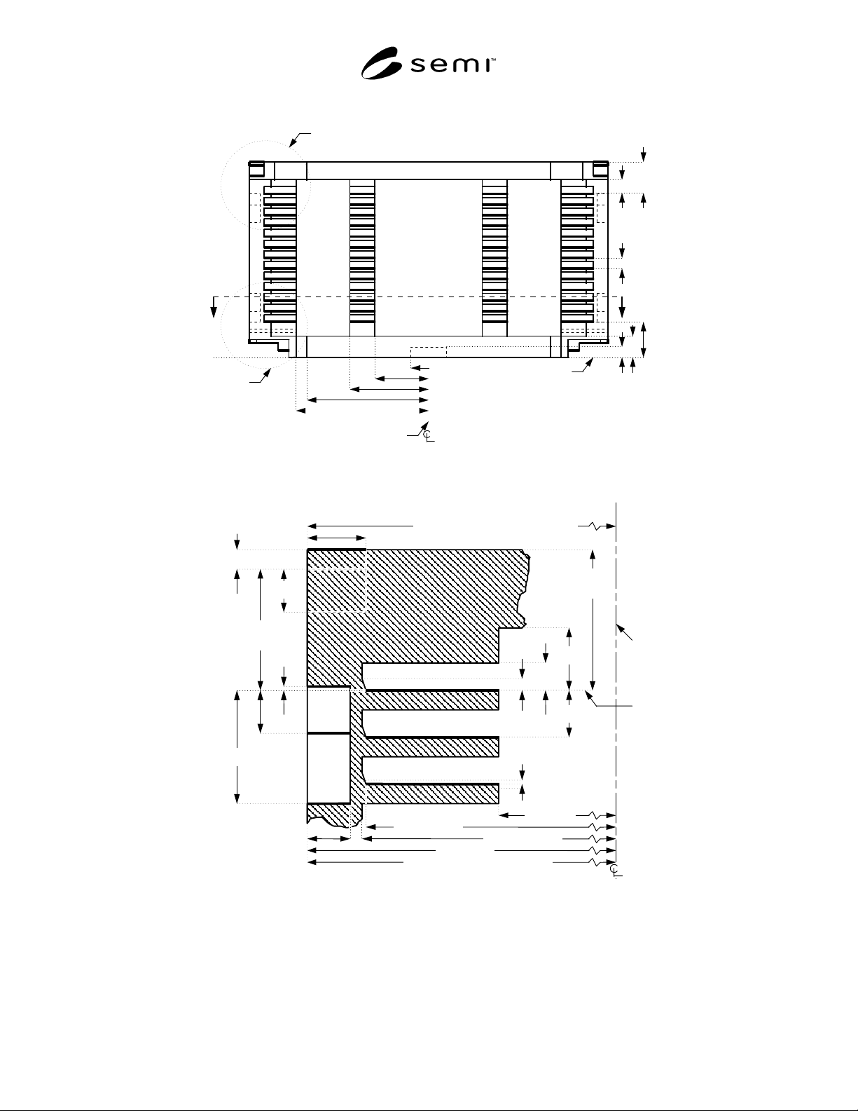
SEMI E1.9-0701 E2 © SEMI 1994, 2004 9 cross- section in Figure 1 detail in Figure 12 detail in Figure 10 horizontal datum pla ne z 8 =33 z 5 ≥ 10 z 18 ≤ 30 (to top) z 15 ≥ 13 z 6 ≤ 21 r 7 ≥ 15 x 1 ≥ 50 x 2 ≤ 75 x 6 ≤ 112…
SEMI E1.9-0701
E2
© SEMI 1994, 2004 8
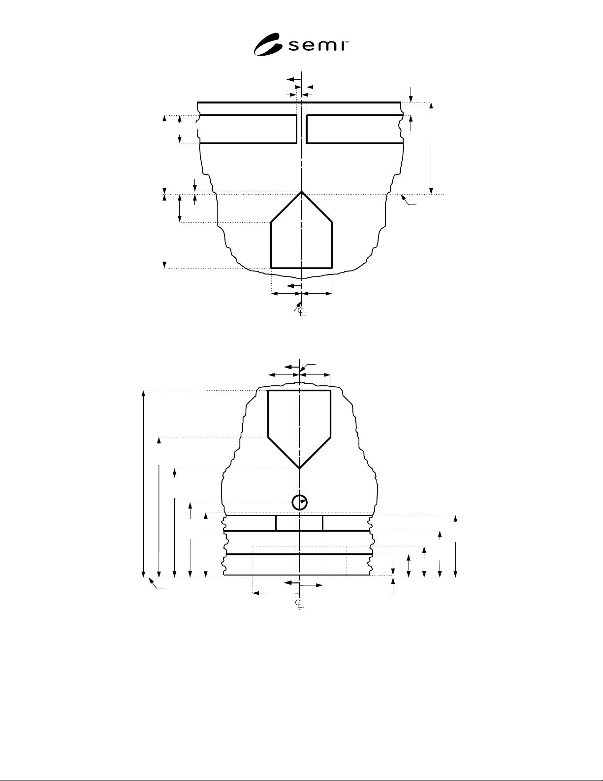
facial datum plane
z14 =1±1
z18 ≤30
(to top of
cassette)
z21 =9±1
z13 =24±1
top
nominal
wafer
plane
z17
=26±1
y8 =2±0.5
y7 =2±0.5
y2 =10±1y3 =10±1
cross-section in
Figure 10
z24 =4±1
(to top of
flange)
z16 =9±1
Figure 7
Top Side View Detail
z
5
≥
10
z
3
=7±1
z
9
=45±1
z
22
≥
20
z
19
=24
z
7
=35±1
horizontal datum plane
z
6
≤
21
z
4
=15±1
z
1
≥
0
z
2
≤
2
(at sensor pad)
z
20
=60±1
r
9 =2.5±0.5
r
8 =7.5±1
facial datum plane
y
2 =10±1
y
3 =10±1
r
7
≥
15
cross-section in Figure 11
Figure 8
Bottom Side View Detail
SEMI E1.9-0701
E2
© SEMI 1994, 2004 9
cross-
section
in
Figure
1
detail in
Figure 12
detail in
Figure 10
horizontal datum plane
z8
=33
z5
≥10
z18
≤30
(to
top)
z15
≥13
z6
≤21
r7 ≥15
x1 ≥50
x2 ≤75
x6 ≤112.5
x12 ≥125
z12
=10
bilateral datum plane
Figure 9
Front View of Cassette
z
24 =4±1
(to top of
flange)
z
16 =9±1
z
14 =1±1
z
15
≥
13
z
18
≤
30
(to top)
z
11
≥
6
z
21 =9±1
z
12 =10
x
3
≥
125
bilateral
datum
plane
x
4
≥
8
x
7
≥
12
z
13 =24±1
z
23
≤
3
r
11 =166±1 (at top robotic flange)
top
nominal
wafe
r
plane
z
17
=26±1
z
10 =±0.5
(height of
wafer bottom)
r
3
≥
r
2 + 1
x
9
≤
167
x
10 =166±1 (at side grip pits)
r
2 =152
+1
–0
Figure 10
Upper Cross-Section at Facial Datum Plane
SEMI E1.9-0701
E2
© SEMI 1994, 2004 10
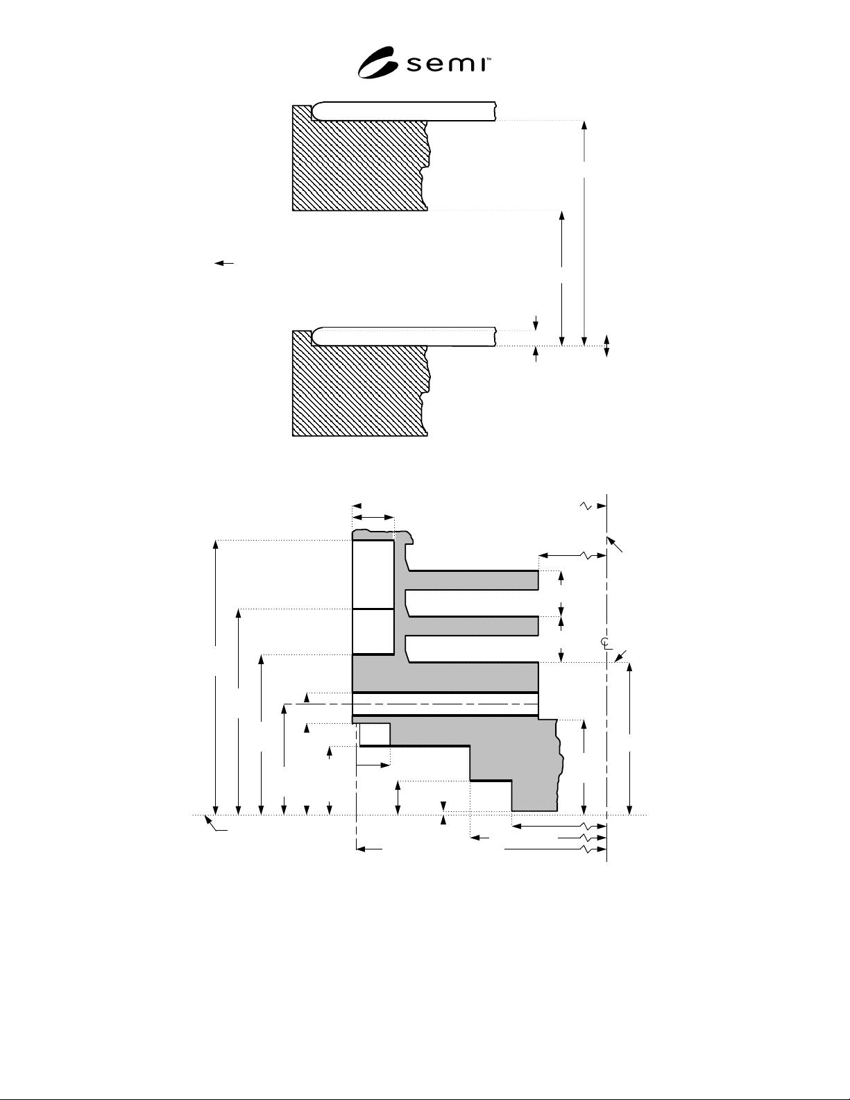
Wafer
z10
=±0.5
z29
≤
0.7
z12 =10
z11
≥
6
front side of the cassette where wafers are accessed
Figure 11
Optional Feature to Prevent Wafer Creep-Out
z3
=7±1
z9
=45±1
z8 =33
x3 ≥125
z12 =10
z12 =10
bilateral
datum
plane
z19
=24
z7
=35±1
horizontal datum plane
z6
≤21
z4
=15±1
(if ω=0)
z1 ≥0
z2 ≤2
(at sensor pad)
x9 ≤167
x10 =166±1 (at side grip pits)
x15 ≤132
x16 =140±1
z20
=60±1
r9 =2.5±0.5
r8 =7.5±1
x4 ≥8
bottom
nominal
wafer
plane
x11 =166 (to origin of r8)
z22
≥20
Figure 12
Lower Cross-Section at Facial Datum Plane
6.7.3 If a wafer is placed in the wafer set-down volume
and is then pushed toward the rear of the cassette, then
the entire bottom of the wafer must be contained in the
wafer pick-up volume. However, if the wafer is not
pushed toward the rear of the cassette (or the cassette is
not tilted back during transport), then the wafer may
only be somewhere within the wafer extraction volume.
The wafer pick-up volume is defined by a cylindrical
section with radius r1 and a main axis at the nominal
wafer center line. Its top and bottom are the upper and